


12
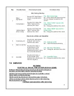
4. Place in operation the appliance being inspected. Follow the lighting instructions. Adjust
thermostat operation so appliance will operate continuously.
5. Test for spillage at the draft regulator outlet / draft hood opening after 5 minutes of main
burner operation. Use the flame of a match or candle, or smoke from a cigarette, cigar,
or pipe.
6. After it has been determined that each appliance remaining connected to the common
venting system properly vents when tested as outlined above, return doors, windows
exhaust fans, fireplace dampers and any other gas-burning appliance to their previous
condition of use.
7. Any improper operation of the common venting system should be corrected so the
installation conforms with the National fuel gas code ANSI Z223.1/NFPA 54 and/or the
Natural gas and propane installation code CAN/CSA B149.1. When resizing any portion
of the common venting system, the common venting system should be resized to
approach the minimum size as determined by the appropriate tables in chapter 13 of the
National fuel gas code ANSI Z223.1/NFPA 54 and/or the Natural gas and propane
installation code CAN/CSA B149.1.
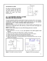
•
Vent installations shall be in accordance with Part 10, Venting of Equipment, and
Part 13, Sizing of Category I Venting Systems, CSA B199.1, of the National Fuel
Gas Code, ANSI Z223.1/NFPA 54 , and/or Section 7, Venting Systems and Air
Supply for Appliances, and Appendix C, Vent Sizing Tables for Category I Natural
Gas and Propane Appliances, of the Natural Gas and Propane Installation Code,
CSA B149.1, the local building codes, furnace and the vent manufacturer’s
instructions.
•
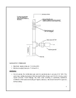
Multistory common venting is not permitted for the KHM gas fired furnaces.
•
KHM gas fired furnaces MUST be vented vertically.
•
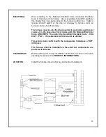
The furnace shall be connected to a factory built chimney or vent complying with
a recognized standard, or a masonry or concrete chimney lined with a lining
material acceptable to the authority having jurisdiction. Venting into an unlined
masonry chimney or concrete chimney is prohibited.
•
For furnaces for connection to gas vent or chimneys such as the KHM furnace, vent
installation must be in accordance with “Venting of equipment” of the National fuel gas code
ANSI Z223.1/NFPA 54 or “Venting systems and air supply for appliances” of the Natural gas
and propane installation code CAN/CSA B149.1, or applicable provisions of the local building
codes.
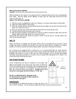
Vent connectors serving appliances vented by natural draft shall not be connected into any
portion of mechanical draft system operating under positive pressure.
Use of cellular core PVC (ASTM F*891), cellular core CPVC or Radel (Polyphenolsulfone) in
venting systems shall be prohibited.


