IOG 2835.50
R
12
4
22
B
24
A
22
12
14
15
K1
K1
19
5
1)
2)
3)
4)
5)
6)
7)
8)
1)
2)
3)
4)
5)
6)
7)
8)
Cut the module cover (C) with a sharp knife approx. ¼" (6mm) above the
finished flooring – see fig. 2.1 and 2.2.
Undo 6 screws (A) and remove the insert for the leakage test (B).
In place of the insert (B), place the faucet pillar (1). Pay attention if o-rings (OR)
are properly placed in the pillar adapter grooves; if necessary lubricate
the seals (OR) with a silicone lubricant.
Position the mounting ring (2) against the connecting module (R) so that the
mounting holes in the ring and module were in axis with one another. Fix the ring
to the module with the screws (A). Before tightening up the screws (A)
make sure that the faucet pillar (1) is placed properly.
Remove the protective foil from the faucet pillar (1). Slightly dampen the gasket
in the rosette (3) with water and soap. Pull (from the top) the rosette over the
faucet pillar and gradually pull it down, to the floor level – see fig. 3.2. Clean the
column with a soft cloth and remove the remaining water and soap.
Pull the faucet body (downwards) (4) over the pillar ferrule (1). Note! Make sure
the faucet pillar (1) is positioned correctly in relation to the faucet body (4).
When the faucet body (4) is set on the right position in relation to the pillar (1)
retaining screws (6) should be screwed using the Allen key (K1) –
see fig. 3.4.
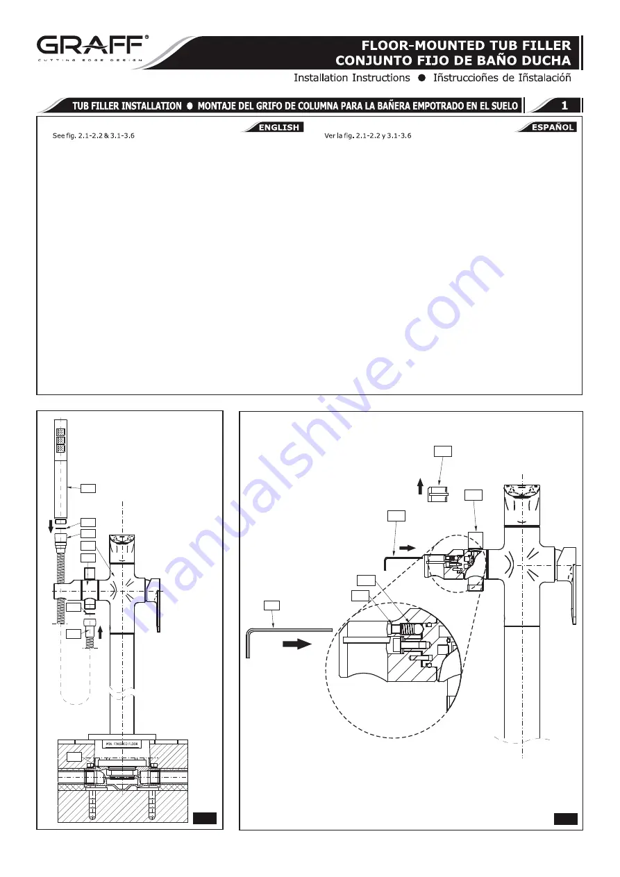
Slide the spout (25) into the faucet body socket (4) from above. Be careful not
to damage the o-ring seals on the spout connecting piece. When the spout (25)
is set on its position, screw the retaining screw (6) with the Allen key (K1) – see
fig. 3.5
Put the shower hose nut (22) on the screwed ferrule of the holder (12) and do
not forget to put the flat seal (A) on its position. Screw the second shower hose
nut – conical nut on the handshower ferrule (24) and do not forget to put the flat
seal (B) on the position. Then slide the handshower (24) into the holder (12) -
see fig. 3.6.
If a worn out mixing tap needs to be replaced, remove the lever screw with the
Allen key, remove the lever (10) with the shroud (9). Remove the nut (8) with a
30 mm spanner and remove the mixing tap (7). Reinstall by reversing the
disassembly steps - see fig. 5.
9)
Corte con un cuchillo afilado la protección del módulo (C) a la altura de unos ¼"
(6mm) sobre el nivel del suelo – mire el dibujo 2.1 y 2.2.
Destornille 6 tornillos (A) y desmonte el elemento para el test de hermeticidad (B).
Donde está el cartucho (B) coloque la columna del grifo (1). Fíjese en la posición
adecuada de juntas o-ring (OR) en las ranuras del adaptador de la columna, si
lo considera necesario antes del montaje lubrifique levemente las
juntas (OR) con el lubricante de silicona.
Coloque el anillo de fijación (2) respecto al módulo de conexión (R) así que los
orificios de montaje en el anillo y en el módulo se encuentren en el mismo eje.
Sujete el anillo al módulo con tornillos (A). Antes de apretar los tornillos (A)
asegúrese que la columna del grifo (1) se encuentre en la posición adecuada.
Quite la lámina de protección de la columna del grifo (1). Moje levemente la
junta en la roseta (3) con agua y jabón. En la columna del grifo desde arriba
meta la roseta y vaya bajándola hasta el nivel del suelo – fig. 3.2. Limpie la
columna con un trapo suave y quite los restos del agua y jabón.
Desde arriba en el tubo corto de la columna (1) meta despacio el cuerpo del grifo
(4). ¡Atención! Preste atención en la posición correcta de la columna del grifo (1)
en relación al cuerpo del grifo (4). Cuando el cuerpo del grifo (4) esté posiciona-
do correctamente respecto a la columna (1) aprieta los tornillos de
fijación (6) con una llave allen (K1) – fig. 3.4.
Desde arriba coloque el caño (25) en el cuerpo del grifo (4). Preste atención para
no lastimar la junta o-ring en la conexión del caño. Cuando el caño (25) esté
colocado correctamente apriete el tornillo de fijación (6) con una llave
allen (K1) – fig. 3.5.
Sobre el tubo corto de la regadera (12) enrosque la tuerca de la manguera de la
ducha (22), recordándose poner la junta plana (A ), enrosque otra tuerca de la
manguera – tuerca cónica – en el tubo corto de la regadera de la ducha (24),
recordándose poner la junta plana (B ). Coloque la regadera de la ducha
(24) en su porta (12) – fig. 3.6.
En caso de reemplazar el mezclador usado, destornillar con llave Allén el tornillo
de la palanca y, luego, quitar la palanca (10) y la caperuza (9). Destornillar la
tuerca (8) con el empleo de la llave 30 mm y sacar el mezclador
(7). El montaje del todo deberá realizarse en orden inverso - fig. 5.
9)
3.6
4
Rev. 2 July 2014


