background image

Empty and Flush Entire System (new system or end of job) 

36

3A4381M

Empty and Flush Entire System
(new system or end of job)

NOTE:

If the system includes heaters and heated hose, 
turn them off and allow to cool before flushing. Do 
not turn on the heaters until the fluid lines are clear 
of solvent.

Cover fluid containers and use the lowest possible 
pressure when flushing to avoid splashing.

Before color change or shutdown for storage, 
circulate the solvent at a higher flow rate and for a 
longer time. Change the solvent when it gets dirty.

To only flush the fluid manifold, see 

Flush Mix 

Manifold, Hose, and Spray Gun

, page 34.

If the machine is inoperable, use drain plugs on the 
pump inlet fittings.

Guidelines

Flush new systems if the coating materials will be 
contaminated by mineral oil. Follow the 

Flush System 

Procedure

 on page 38 to ensure mineral oil is removed. 

Flushing will help prevent materials from settling or 
gelling in the pumps, lines, and valves. Flush the system 
when any of the following situations occur.

Anytime the system will not be used for more 
than one week (depending on materials used)

If the materials used have fillers that will settle

If using materials that are moisture sensitive

Before servicing

If the machine is going into storage, replace the 
flush solvent with light oil. Never leave the 
equipment empty of any fluid.

Empty System Procedure

1. Follow 

Prime Empty System

 steps 3-8, page 27.

2. If your system is equipped with a solvent flush 

pump, follow 

Flush Mix Manifold, Hose, and 

Spray Gun

 on page 34. 

3. If your system is not equipped with a solvent flush 

pump, follow the 

Pressure Relief Procedure

 on 

page 26 before servicing the system.

4. Engage the trigger lock.

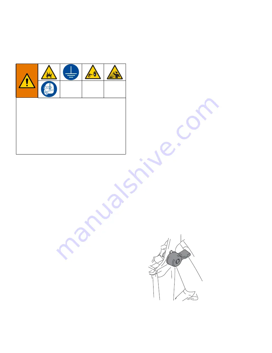
To avoid fire and explosion, always ground equipment 
and waste container. To avoid static sparking and 
injury from splashing, always flush at the lowest 
possible pressure. Hot solvent may ignite. To avoid fire 
and explosion:

Flush equipment only in a well-ventilated area

Ensure main power is off and heater is cool before 
flushing 

Do not turn on heater until fluid lines are clear of 
solvent

ti1949a

Summary of Contents for XP-hf 572407

Page 1: ...professional use only Not approved for use in explosive atmospheres or hazardous locations except where indicated in the Models section See page 11 for models numbers descriptions and agency approval designations Important Safety Instructions Read all warnings and instructions in this manual before using the equipment Save these instructions WL E 3A4381M EN ...

Page 2: ...to Spraying or Re Prime After a Pump Runs Dry 30 Spray 31 B Component Adjustable Fluid Restrictor 33 Flush Mixed Material 34 Flush Mix Manifold Hose and Spray Gun 34 Empty and Flush Entire System new system or end of job 36 Park 39 Shutdown 39 System Verification 40 Maintenance 41 Hose Electrical Resistance 41 Filters 41 Seals 41 Cleaning Procedure 41 Change the Mix Ratio 41 Troubleshooting 42 Pum...

Page 3: ...1 Viscon HP Heater Adapter Kit Instructions Parts 3A5313 Xtreme Wrap Water Heated Hose Instructions Parts 3A5314 Hose Heat Circulation XP and XP hf Kit Instructions Parts Solvent Flush 310863 Feed and Solvent Flush Kits Instructions Parts 312794 Merkur Pump Assembly Instructions Parts Accessories and Kits 3A3320 XP and XP hf PressureTrak Kit Instruction Parts 3A1331 XP Pressure Monitor Kit Instruc...

Page 4: ...revent fire and explosion Use equipment only in well ventilated area Eliminate all ignition sources such as pilot lights cigarettes portable electric lamps and plastic drop cloths potential static sparking Ground all equipment in the work area See Grounding instructions Never spray or flush solvent at high pressure Keep work area free of debris including solvent rags and gasoline Do not plug or un...

Page 5: ...top or deflect leaks with your hand body glove or rag Follow the Pressure Relief Procedure when you stop spraying and before cleaning checking or servicing equipment Tighten all fluid connections before operating the equipment Check hoses and couplings daily Replace worn or damaged parts immediately MOVING PARTS HAZARD Moving parts can pinch cut or amputate fingers and other body parts Keep clear ...

Page 6: ...equipment Keep children and animals away from work area Comply with all applicable safety regulations PERSONAL PROTECTIVE EQUIPMENT Always wear appropriate personal protective equipment and cover all skin when spraying servicing equipment or when in the work area Protective equipment helps prevent serious injury including long term exposure inhalation of toxic fumes mists or vapors allergic reacti...

Page 7: ... the work area must wear appropriate respiratory protection Always wear a properly fitting respirator which may include a supplied air respirator Ventilate the work area according to instructions in the fluid manufacturer s SDSs Avoid all skin contact with isocyanates Everyone in the work area must wear chemically impermeable gloves protective clothing and foot coverings as recommended by the flui...

Page 8: ...es used in your equipment requires special attention to avoid equipment damage and downtime When changing materials flush the equipment multiple times to ensure it is thoroughly clean Always clean the fluid inlet strainers after flushing Check with your material manufacturer for chemical compatibility When changing between epoxies and urethanes or polyureas disassemble and clean all fluid componen...

Page 9: ...pplied to only one of the fluid pumps Cart Mounted Systems Only Maximum air pressure set point blow off valves are provided to limit maximum fluid pressure Do not remove these valves Color coded automatic over pressure relief valves are used on cart mounted systems to dump excess fluid pressure back to the supply Never plug these return hoses See Fluid Circulation Manifold with Over Pressure Relie...

Page 10: ...Ease of use Ease of service and greater access to lowers Using an XP hf system or components on the system not approved for hazardous locations or explosive atmospheres may result in a fire or explosion hazard The XP hf systems are not approved for use in hazardous locations unless the base model all accessories all kits and all wiring meet local state and national codes See Wire Systems with Expl...

Page 11: ... L097C0 242 2 6 9 8 Silver 85 0 59 5 9 86 1 7250 50 500 xxx20x 2 1 L18AC0 L090C0 270 2 8 10 6 Silver 95 0 65 6 5 76 1 7250 50 500 xxx25x 2 5 1 L18AC0 L072C0 252 2 6 9 8 Silver 90 0 62 6 2 81 1 7250 50 500 xxx30x 3 1 L22XC0 L072C0 292 3 0 11 3 Silver 100 0 7 7 71 1 7100 49 490 xxx40x 4 1 L22XC0 L054C0 274 2 8 10 6 Silver 95 0 65 6 5 76 1 7250 50 500 Fourth and Fifth Digits Pump Ratio A B A Side Pum...

Page 12: ...x HAZ EX xxxxx3 x x x 240 V x HAZ EX xxxxx4 x x x x 240 V x HAZ EX xxxxx5 x x x x 240 V x x ORD xxxxx6 x x x x 240 V x 240 V HAZ EX xxxxx7 x x x x 240 V x x 240 V ORD xxxxx8 x x x x 480 V x x ORD xxxxx9 x x x x 480 V x x 480 V ORD Pump Packages without Pump Lowers Includes Part System Ratio Maximum Fluid Working Pressure psi MPa bar Cart XTRxxx Spray Gun and 35 ft 10 7 m Supply hose not attached 5...

Page 13: ...luid Control Assembly see page 15 P Pump Tie Rods R Motor Adapter Plate S Adjustable Packing Nuts with Wet Cups T Yoke with Rod Bearings V Connecting Rod Nut W Static Mixer Tubes with Replaceable Plastic Elements X Motor Position Indicator Bracket see Motor Position page 22 Y Over Pressure Rupture Disc only 145cc pumps or smaller ZB Air Motor Ground Wire ZD Solvent Pump Ground Wire ZL Gun and Hose...

Page 14: ...ial J 7 Gallon Hoppers green B side shown M Handle lift to release U Recirculation Lines BA Solvent Flush Pump ZA Pressure Trak ZC Junction Box ZF Circulation Pump Reservoir ZG Circulation Pump ZH Viscon HP Hose Water Heater ZK Solvent Prime Flush Valve ZM Heater ON OFF Switches WL F 0 0 8 Model 572407 Shown ...

Page 15: ... Recirculation Handle shown closed AD Solvent Flush Valve AE Dual Shutoff Handle shown closed AF Fluid Pressure Gauges AH Recirculation Fittings AJ B Component Adjustable Fluid Restrictor see page 33 AK A and B Mix Manifold Check Valves AL Solvent Inlet Check Valve AM Automatic Spring Loaded Color Coded Over Pressure Relief Valves with grease fittings see page 49 AH ti19167a Standard Mix Manifold ...

Page 16: ...er ending in zero 0 to make a complete system Key CA Motor Shutoff Valve Relieving CB Motor Air Pressure Regulator CC Air Filter with Auto Drain CD Main Motor Air Pressure Gauge CE Filtered Air Distribution Manifold CF Main Inlet Air Shutoff Valve CG Motor Air Pressure Relief Valve CH Main Air Inlet WL E ...

Page 17: ...BD Muffler BE Solvent Prime Valve BF Solvent Outlet Hose BG Solvent Circulation Hose BH Solvent Pump Wet Cup BA BB BD BG BF BE suction hose not shown BH Key DA Solvent Pump Air Shutoff Valve Relieving DB Solvent Pump Air Pressure Regulator DC Solvent Pump Air Pressure Gauge DD Solvent Pump Air Outlet DE Solvent Pump Air Inlet WL D ...

Page 18: ...s circulation and pump priming Mix Manifold AB Combines A and B fluid into one fluid line Recirculation Handle AC Directs fluid flow for circulation or mixing Move to open position to relieve fluid pressure prime pumps and circulate material in hoppers Move to closed position to spray mixed material Dual Shutoff Handle AE Controls A and B fluid flow for mixing and dispensing Close before flushing ...

Page 19: ...n tube kits if you are feeding material from drums or remote hoppers See your circulation and return tubes kit manual if you are feeding urethane material 7 Connect the feed pumps fluid strainers and air hoses as necessary For systems without hoppers see your feed pump and agitator kit manual 8 Connect the fluid hose assembly including the static mixers whip hose and gun See Connect Static Mixers ...

Page 20: ...pump to the ground stud GS on the solvent pump BA Air and fluid hoses use only static dissipation type hoses with a maximum of 300 ft 91 m combined hose length to ensure grounding continuity Check electrical resistance of hoses regularly If total resistance to ground exceeds 29 megohms replace hose immediately Air compressor follow manufacturer s recommendations Spray gun ground through connection...

Page 21: ... positions shown in the image below for the power source used NOTE Terminal jumpers are located inside the electri cal enclosure door 8 Verify that all items are connected properly as shown below then close the electrical enclosure door NOTE See the Junction Box XP Installation and Parts manual for detailed instructions NOTE 350 415 VAC are not designated to operate from 480 VAC power source All e...

Page 22: ...ecific motor positions for each mix ratio setting To Adjust the position of the air motor 1 Perform the Check Motor Position procedure If the position is incorrect continue to the next step 2 Loosen the eight fasteners and remove the two pump guards 3 Loosen the three nuts 107 below the motor tie rods 4 Slide the tie rods 102 and motor E until the indicator lines are aligned with your ratio 5 Tigh...

Page 23: ...ect Static Mixers Gun Hoses 1 Connect the outlet of the two primary static mixer tubes with mixer elements W to the fluid mix hose 25 cleanup mixer 27 28 whip hose 30 and spray gun 31 2 Add mixed material hose as necessary between the mix hose 25 and cleanup mixer 27 28 WL D CH NOTICE To prevent creating a flare on the mixer tube do not use a union swivel end on the mix tube inlet 25 W 27 28 30 31...

Page 24: ... colors match when connecting the fittings 6 Connect the mix manifold MM to the remote manifold carriage MC heater block HB and bracket using two screws 9 7 Connect the resin and hardener hoses to the mix manifold 8 Connect the extension glycol tubing from the hose bundle to the heater block HB Cut the tubing squarely behind only one of the u fittings Connect the two union fittings 10 to the hose ...

Page 25: ...Setup 3A4381M 25 Connecting Hoses WL D B WL D 4 04 0 00 A B A RED RED BLUE BLUE ...

Page 26: ...d before cleaning checking servicing or transporting equipment 11 If you suspect the spray tip or hose is clogged or that pressure has not been fully relieved after following the steps above very slowly loosen tip guard retaining nut or hose end coupling to relieve pressure gradually then loosen completely Clear hose or tip obstruction 12 If static mixer whip hose and gun cannot be flushed because...

Page 27: ...ly mixed homogeneous and pour able prior to adding to the hopper Stir the hardeners back into suspension prior to adding material to hopper 2 Fill the A and B hoppers with proper materials Fill the A side blue with major volume of material fill the B side green with minor volume of material unless 1 1 mix ratio 3 Move the recirculation lines U to empty containers 4 Close the dual shutoff handle AE...

Page 28: ...til clean fluid comes out of the A and B recirculation lines 7 Decrease air pressure Close the motor shutoff valve CA 8 Move the recirculation lines U back to the correct hopper J 9 If using heaters heat fluid throughout system before spraying See Recirculate Prior to Spraying or Re Prime After a Pump Runs Dry page 30 WL E B A CB CA WL D WL E CA WL E 8 ...

Page 29: ...rigger the gun into a grounded metal pail while holding against a pail Use a pail lid with a hole to dispense through Seal around the hole and gun with a rag to prevent splash back Be careful to keep fingers away from the front of the gun 8 Open the solvent pump air valve DA Slowly turn the solvent pump air regulator DB clockwise to prime the solvent pump and push air out of the mix hose and gun T...

Page 30: ... are in the correct hoppers J 4 Lower to open the recirculation valve handle AC 5 Turn down the air pressure regulator CB and then open the motor air shutoff valve CA Use the air pressure regulator to slowly increase the air pressure to the pumps to 15 30 psi 1 2 bar until they start running slowly 6 Run the pumps for a few minutes or until the material has reached the desired temperature See Heat...

Page 31: ...Close the motor air pressure regulator CB and decrease to zero 3 Close the recirculation handle AC and the solvent flush valve AD Open the dual shutoff handle AE 4 Adjust the motor air regulator CB to 30 psi 0 21 MPa 2 1 bar minimum 5 Remove tip Disengage the trigger lock and trigger the gun while holding against a grounded metal pail Use a metal pail lid with a hole to dispense through to avoid s...

Page 32: ...gauge readings frequently during operation A change in gauge readings indicates a change in system performance NOTE A pressure drop occurs during pump stroke changeover It should be quick and synchronous Flush the mix manifold as necessary during the day s operation 9 Follow Flush Mixed Material page 34 when you are finished spraying or before potlife expires NOTE Mixed material potlife or working...

Page 33: ...x hose to the spray gun It can also be used in the ratio check procedure If the mix manifold AB is mounted on the machine you do not need to adjust the restrictor Leave the restrictor stem open two turns minimum from fully closed To Adjust the Restrictor Adjust the restrictor stem clockwise while spraying until you see a slight rise in the B side pressure gauge The point where the pressure starts ...

Page 34: ...off valve CA to turn off the pump air motor and reduce air pressure Engage trigger lock Remove the spray tip and soak in solvent 4 Lift to close the dual shutoff handle AE 5 Open the solvent pump air valve DA Slowly turn the solvent pump air regulator DB clockwise to increase air pressure To avoid fire and explosion always ground equipment and waste container To avoid static sparking and injury fr...

Page 35: ...g to prevent splash back Be careful to keep fingers away from the front of the gun Continue flushing until clean solvent dispenses 8 Close the solvent pump air valve DA 9 Hold a metal part of the gun against a grounded metal pail and trigger the gun to relieve pressure Close the solvent flush valve AD after relieving the pressure 10 Engage the trigger lock Disassemble and clean the spray tip with ...

Page 36: ...es and valves Flush the system when any of the following situations occur Anytime the system will not be used for more than one week depending on materials used If the materials used have fillers that will settle If using materials that are moisture sensitive Before servicing If the machine is going into storage replace the flush solvent with light oil Never leave the equipment empty of any fluid ...

Page 37: ...open the recirculation handle AC and increase the motor air pressure regulator CB pressure to 20 psi 138 kPa 1 38 bar 8 Open the motor air shutoff valve CA NOTE If the system does not start with static pressure increase the air pressure by 5 psi 35 kPa 0 35 bar increments To avoid splashing do not exceed 35 psi 241 kPa 2 4 bar 9 Run the pumps until the A and B hoppers J are empty Salvage the mater...

Page 38: ...gh the mix manifold valves and out the gun 7 Turn off the air motor 8 Lift to close the dual shutoff handle AE 9 Remove pump fluid filters if installed and soak in solvent Clean and replace the filter cap Always replace the filter o rings See your Xtreme pump manual 10 Fill the A and B pump packing nuts with TSL Also always leave some type of fluid such as solvent or oil in the system to prevent s...

Page 39: ...r CB counterclockwise Lower to open the recirculation handle AC Shutdown 1 Flush mix manifold hoses and gun See Flush Mix Manifold Hose and Spray Gun page 34 2 Make sure the air motor shutoff valve CA is closed 3 Make sure the solvent air shutoff valve DA is closed and the solvent air pressure regulator DB is turned fully counterclockwise 4 Close the solvent flush valve AD and lower re circulation...

Page 40: ...ern s entire length at the time listed on the data sheet Spots that take longer to cure indicate insufficient pump loading leakage or lead lag errors at a remote mix manifold Appearance Test Spray material onto foil Look for variations in color gloss or texture that may indicate improperly catalyzed material Monitor Fluid Supply NOTE To prevent pumping air into the system which causes incorrect pr...

Page 41: ... Relief Procedure on page 26 6 Perform Park and Shutdown procedures page 39 Turn off all power 7 Clean the external surfaces only using a rag soaked in solvent that is compatible with the spray material and surfaces being cleaned 8 Allow enough time for the solvent to dry before using the system Change the Mix Ratio In order to change the mix ratio one or both pumps need to be replaced the air mot...

Page 42: ...or damaged resin pump piston valve or piston packings Clean repair pump see your lower pump manual Pump operates but resin output pressure drops on downstroke Dirty worn or damaged resin pump intake valve Clean repair pump see your lower pump manual Pump operates but resin output pressure drops on both strokes Hardener output restriction Clean unplug hardener side Open manifold restrictor Fluid su...

Page 43: ...bly 258962 see page 63 and over pressure relief valve 302 Pressure and flow surges on upstroke Feed pressure too high Every 1 psi of feed pressure adds 2 psi during upstroke Reduce feed pressure See Dimensions page 72 Fluid outlet pressure gauges split only at the top changeover if one gauge drops the other will rise Not fully loading one side on upstroke Increase feed pressure on side that droppe...

Page 44: ...l components WL D WL D WL D TROUBLE AREA Resin Pump Leakage 1 Throat packing 2 Piston packing 3 Piston ball check Resin Pump Falling Rising Hardener Pump TROUBLE AREA Hardener Pump Leakage 1 Throat packing 2 Piston packing 3 Piston ball check TROUBLE AREA Resin Pump Leakage 1 Throat packing 2 Intake ball check TROUBLE AREA Hardener Pump Leakage 1 Throat packing 2 Intake ball check Resin Pump Harde...

Page 45: ...ashers 5 under the tie plate 901 5 Use hoist to remove the pump assembly by the lift ring and carefully lift out of cart 1 Remove Displacement Pump 1 Follow the Park procedure and Shutdown procedure on page 39 2 If hoppers are installed remove the hopper and hopper bracket from the cart See Hoppers page 50 3 If feed pumps are installed close the inlet ball valve Remove inlet union 61 4 Remove the ...

Page 46: ... page 47 Replace Air Control Assembly 1 Close the main air shutoff valve on the air supply line and on the system Depressurize the air line 2 Disconnect the air motor air lines and system air line 3 Remove screws 50 Remove the bottom air filter assembly from the cart 4 Remove the upper air control assembly from the air motor 5 Follow the steps in reverse order to reinstall the new air control asse...

Page 47: ...Repair 3A4381M 47 Air Control Assembly FIG 2 Air Control Assembly WL D ...

Page 48: ...osen the two screws 37 that secure the manifold 35 to the cart 1 5 Remove the two screws 37 and fluid circulation manifold 35 from the cart 1 Replace Over Pressure Relief Valves 1 Follow the Park procedure and Shutdown procedure on page 39 2 Ensure handle 312 is in the down position Remove the screws 313 jam nut 304 handles 311 handle rod 312 clips 318 and springs 320 3 Unscrew both over pressure ...

Page 49: ...stall two screws 313 in handles 311 12 Check operation of the handle and valves 13 Operate the handle in and out of the spray and circulate positions 14 Check for clearance with fittings NOTE Both valves should settle firmly into the spray position inward against the seats in the valve Both valve stems should rotate out to their most extended positions when the handle is pulled down to the circula...

Page 50: ...tting 61 and disconnect hopper from pump 5 Remove the recirculation line from the hopper and place in a waste container 6 Lift the hopper off of the mounting bracket 7 Repeat for second hopper Solvent Pump 1 Follow the Pressure Relief Procedure on page 26 2 Disconnect the fluid line and air lines from the solvent pump 3 Loosen the four screws that attach the solvent pump to the cart 1 Lift and pul...

Page 51: ...n HF heater manual to service or repair 4 Reconnect the fluid lines and electrical wiring Replace 1 Follow steps 1 through 2 in the Fluid Heaters Service and Repair section 2 Loosen the four mounting screws lock washers and plain washers on back of the heater Slide the heater up and remove from the cart 3 Replace the heater Follow the steps in reverse order to install a new heater WL D F ...

Page 52: ...Parts 52 3A4381M Parts Complete System 572107 shown WL G TSL B A B A 1 Apply anaerobic pipe sealant to all non swiveling pipe threads ...

Page 53: ...Parts 3A4381M 53 Complete System continued WL H D ...

Page 54: ...adding Non approved accessories voids the Hazardous Area Approvals La modificación de esta máquina o adición de accesorios no autorizados anula la zona peligrosa de idoneidad Modification de cette machine ou de lajout daccessoires non approuv és par les vides de la zone dangereuse approbations E F ...

Page 55: ...Parts 3A4381M 55 Complete System continued G WL G Non Hazardous Location Version Shown SOLVENT PUMP A FLUID HEATER Hazardous Location Version Shown B FLUID HEATER ...

Page 56: ...element 25 pack 3 3 3 3 3 3 3 3 3 21 111218 CAP tube square 4 4 4 4 4 4 4 4 4 22 158491 FITTING nipple 4 4 4 4 4 4 4 4 4 23 15M987 FITTING elbow 60 2 2 2 2 2 2 2 2 2 24 H75003 HOSE 7250 psi 2 2 2 2 2 2 2 2 2 25 H53825 HOSE 5000 psi 25 ft 1 1 1 1 1 1 1 1 1 26 15B729 COUPLING 1 1 1 1 1 1 1 1 1 27 262478 HOUSING mixer 3 3 3 3 3 3 3 3 3 29 150287 COUPLING pipe 1 4 X 3 8 1 1 1 1 1 1 1 1 1 30 H52510 HOS...

Page 57: ...d 240 V hazardous locations 2 2 2 25C961 HEATER fluid 240 V non hazardous locations 2 2 26C475 HEATER fluid 480 V non hazardous locations 2 2 80 185065 ADAPTER cable 2 2 2 81 273096 JUNCTION BOX 240 V non hazardous locations 1 1 273101 JUNCTION BOX 480 V non hazardous locations 1 1 81a 17P846 BRACKET junction box 1 1 1 1 81b 113796 SCREW flanged hd 8 8 8 8 81c 115942 NUT flanged hd 4 4 4 2 81d 17N...

Page 58: ... 6 100101 SCREW 3 8 16 x 1 in 4 4 4 4 4 4 4 4 4 7 113362 WHEEL semi pneumatic 2 2 2 2 2 2 2 2 2 8 154628 WASHER 2 2 2 2 2 2 2 2 2 9 113436 RING retaining 2 2 2 2 2 2 2 2 2 10 124410 BEARING sleeve 1 1 1 1 1 1 1 1 1 11 124664 WASHER 1 in 2 2 2 2 2 2 2 2 2 12 262477 AXLE 1 1 1 1 1 1 1 1 1 13 191824 WASHER spacer 4 4 4 4 4 4 4 4 4 14 113807 WHEEL flat free 2 2 2 2 2 2 2 2 2 15 258982 HANDLE cart 1 1 ...

Page 59: ... 2 2 2 2 2 2 2 62 24E872 BRACKET hopper 2 2 2 2 2 2 2 63 124450 CLAMP spring 2 2 2 2 2 2 2 64 15V421 TUBE recirculation 2 2 2 2 2 2 2 65 116704 FITTING adapter 2 2 2 2 2 2 2 66 15T468 LABEL warning 2 2 2 2 2 2 2 67 111192 SCREW cap 4 4 4 4 4 4 4 68 24F126 MODULE air controls 1 1 1 1 1 1 1 69 262392 PUMP solvent 1 1 1 1 1 1 1 70 061132 HOSE nylon 1 1 1 1 1 1 1 71 17Y013 HOSE air 18 in 1 1 1 1 1 1 1...

Page 60: ...NITOR PressureTrak 1 1 1 95 26C414 MODULE air controls 1 1 1 1 1 1 1 1 1 98 126786 TOOL restrictor 1 1 1 1 1 1 1 1 1 99 3A5076 DOCUMENT guide quick start not shown 1 1 1 1 1 1 1 1 1 100 H52506 HOSE recirc 6 ft 2 2 2 2 2 2 2 H52510 HOSE recirc 10 ft 2 2 101 H75005 HOSE Manifold supply 2 2 2 2 2 2 2 107 15M987 FITTING elbow 60 2 2 2 2 2 2 2 108 262482 STRAINER hopper 7 gallon 2 2 2 2 2 2 2 109 17P59...

Page 61: ...th blue threadlock to top thread only Pins and lanyards must be positioned toward the outside of the pump as shown Allow ends of lanyard to hang freely Remove ground screw and washer from motor then use to install cable 2 3 4 5 6 Model 572100 shown Torque together to 230 250 ft lb 312 339 N m Torque together to 95 105 ft lb 129 142 N m 12 13 ...

Page 62: ... 4 922d 15T468 LABEL warning 2 930 124078 CLAMP coupling 2 931 15H108 LABEL safety warning 1 932 111192 SCREW hex head 3 8 16 x 875 in 2 934 184130 COLLAR coupling 1 935 16E882 STRAP lowers 2 940 244524 WIRE grounding assembly 1 Ref Part Description Qty Ref Description 57210x 57215x 57220x 57225x 57230x 57240x Qty 4 PUMP 572100 572150 572200 572250 572300 572400 56 VALVE safety 113498 16M190 11405...

Page 63: ...01 108126 FITTING tee street 1 302 126897 FITTING elbow 1 2 tube x 1 4 NPTM 2 303 126898 FITTING elbow 1 2 tube x 1 2 NPTM 1 304 126899 FITTING 1 2 tube x 1 2 NPTM 1 305 16D939 FITTING nipple reducing 1 306 16R871 BOTTLE overflow 1 2 NPT 1 307 17P088 BRACKET XP HF re circ painted 1 308 206264 VALVE needle 1 309 24P835 PUMP acetal w pvdf check Husky 1 309a 111630 SCREW mach pnh 4 310 113161 SCREW f...

Page 64: ...ous Locations 240V 273095 Non Hazardous Locations 240V 273102 Non Hazardous Locations 480V WL G D E F 5 LQ FP WL D BLACK BLACK GREEN WHITE BLACK 410 410 Orient fittings as shown Tighten cord grip 75 in back from cord cover end Orient the port facing down 3 4 5 ...

Page 65: ...126896 FITTING elbow 1 2 tube x 1 2 NPTF 1 1 1 405 17P759 TUBE 48 in x 0 5 OD nylon 1 1 1 406 126900 FITTING 1 2 tube x 3 8 NPTM 1 1 1 407 17D306 FITTING coupler quick coupling 1 1 1 408 17N600 HARNESS sw5 to hose heat 1 1 409 116171 BUSHING strain relief 1 1 410 122032 NUT wire 2 2 411 166590 FITTING elbow street 1 413 123443 SCREW cap flng hd 4 4 4 414 24N447 BRACKET base heated hose painted 1 1...

Page 66: ...se Heater Fluid Heater B Hopper Heater A Hopper Heater B Fluid Heater A Black Black Black Black Black Black Black Black White White White White White White White White White White White White HOPPER HEATER A Green Green Green Green Green HOPPER HEATER B FLUID HEATER A FLUID HEATER B HOSE HEATER ACCESSORIES ...

Page 67: ...ansfer PFP 2k 1 603 110837 SCREW flange hex 2 604 110996 NUT hex flange head 2 605 126692 FITTING tube NPT x tube 2 606 100721 PLUG pipe 2 608 189285 LABEL safety burn 1 609 120736 SCREW hex flange HD 2 610 126894 FITTING union 1 2 tube x 1 2 tube 2 611 054960 TUBE red nylon 0 375 in 9 5 mm ID 1 5 ft 1 612 054961 TUBE blue nylon 0 375 in 9 5 mm ID 1 5 ft 1 Supplied loose not installed Replacement ...

Page 68: ...ING pipe 1 707 157350 ADAPTER 4 708 115781 CAP PLUG 4 709 17N486 FITTING elbow 1 in npt 1 710 17N462 FILTER air 1 in npt 1 710a 116635 FILTER element not shown 1 711 113163 VALVE ball vented 1 0 2 712 127784 COUPLING universal 1 in nptm 1 713 127785 COUPLING universal 1 in nptf 1 714 16W586 CABLE lanyard whip check 1 715 101689 GAUGE press air 1 716 16P338 SCREW mach serrated hex head 4 717 26C343...

Page 69: ...rculation Overpressure Valve see page 49 XP50 hf 262809 gold XP70 hf 262520 silver 15K692 Seal Mix Manifold Check Valve Cartridge NOTE 15K692 must be replaced when cleaning the check valves 1 2 in Mix Manifold Inlet Ball Valves 24M601 Ball valve repair kit 262740 Spare valve no handle 262739 Spare valve single handle 248927 Spare Mix Elements pack of 25 1 2 in OD x 12 element acetal plastic 248837...

Page 70: ...e your feed pump and agitator kit manual for more information 5 1 Feed Pump Kit 256276 For supplying viscous materials from a drum to XP hf system See your feed pump and agitator kit manual for more information 10 1 Drum Feed Kit 256433 For supplying highly viscous material from a 55 gallon drum to XP hf system See your feed pump and agitator kit manual for more information Gravity Feed Kit 262820...

Page 71: ...Feed Kit 256232 One T2 pump feed kit and one Twistork agitator kit for mixing and supplying viscous materials from a 55 gallon drum to XP hf system See your feed pump and agitator kit manual for more information Wall Line Powered Pressure Monitor Kit 26C008 Air Turbine Powered Pressure Monitor Kit 26C009 Automatically monitors difference between A and B pressures when at spray pressure and shuts d...

Page 72: ...Dimensions 72 3A4381M Dimensions System Dimensions WL E LQ FP LQ FP LQ FP LQ FP Top View Side View ...

Page 73: ...sions Pump Package Part Maximum Width A Maximum Depth B Maximum Height C XP hf with XL 10000 Air Motor 572100 572150 572200 572250 572300 572400 573100 573150 573200 573250 573300 573400 18 in 46 cm 24 in 61 cm 48 in 122 cm A B C WL D ...

Page 74: ...Dimensions 74 3A4381M Floor Mounting Dimensions Top View 6 75 in 17 1 cm 16 9 in 42 9 cm 40 0 in 101 6 cm 15 25 in 38 7 cm 22 0 in 55 8 cm 32 0 in 81 2 cm ...

Page 75: ...er Mounting Hole Dimensions The dimensions below is the minimum opening size for mounting a bare proportioner WL D LQ FP LQ FP LQ FP LQ FP LQ FP LQ FP LQ FP LQ FP LQ FP LQ FP LQ FP LQ FP LQ FP LQ FP LQ FP 9 64 in 24 4 cm LQ FP LQ FP LQ FP ...

Page 76: ...Dimensions 76 3A4381M Wall Mount Bracket 262812 Dimensions LQ FP LQ FP LQ FP LQ FP LQ FP ti19046c ...

Page 77: ...Dimensions 3A4381M 77 Floor Stand 24M281 Dimensions ti19047a 21 2 in 53 8 cm 30 3 in 77 0 cm 17 8 in 45 1 cm 32 7 in 82 9 cm ...

Page 78: ...w XP70 75 scfm at 100 psi gpm 2 12 m3 min at 7 bar 0 7 MPa XP50 60 scfm at 100 psi gpm 1 7 m3 min at 7 bar 0 7 MPa Air supply pressure range 30 100 psi 0 2 0 27 MPA 2 0 6 7 bar Electrical Specifications Configurable Voltage Phase Hz See Connect Power on page 19 Full Load Amps See Power Cord Requirements on page 21 Filtration Air inlet filtration 40 micron filter separator included XP pump outlets ...

Page 79: ... with Hoppers Solvent Pump A B Hazardous Location Heaters xxxxx4 665 lb 302 kg Cart Unit with Hoppers Solvent Pump A B Non Hazardous Location Heaters Junction Box xxxxx5 715 lb 324 kg Complete Unit with A B Hose Hazardous Location Heaters Hose Circulation Pump Pressure Trak xxxxx6 735 lb 333 kg Complete Unit with A B Hose Non Hazardous Location Heaters Junction Box Hose Circulation Pump Pressure T...

Page 80: ... material or workmanship repairs will be made at a reasonable charge which charges may include the costs of parts labor and transportation THIS WARRANTY IS EXCLUSIVE AND IS IN LIEU OF ANY OTHER WARRANTIES EXPRESS OR IMPLIED INCLUDING BUT NOT LIMITED TO WARRANTY OF MERCHANTABILITY OR WARRANTY OF FITNESS FOR A PARTICULAR PURPOSE Graco s sole obligation and buyer s sole remedy for any breach of warra...

Reviews: