


Setup
3A0420V
23
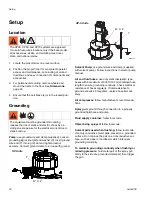
Connect Air Supply
NOTE: For XP systems only.
1. Connect the air supply hose to the 3/4 npt(f) air filter
inlet (C).
NOTE: Use a 3/4 in. (19.1 mm) ID minimum air hose.
Air consumption is 75 cfm per gallon per minute
spraying. Do not use pin fitting type quick discon-
nects.
2. Remove plugs as necessary for solvent pump and
feed supply pump air hoses. See pump manuals for
setup instructions. See F
Connect Hydraulic
Supply/Return Lines
NOTE: For XP-h systems only.
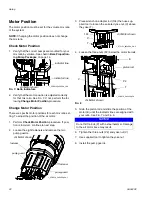
Connect Static Mixers, Gun, and
Hoses
1. Connect the outlet of the two primary static mixer
tubes with mixer elements (W) to the fluid mix
hose (25), cleanup mixer (27, 28), whip hose (30),
and spray gun (31). See F
2. Add mixed material hose as necessary between the
mix hose (25) and cleanup mixer (27, 28).
Connect Fluid Hose Bundles
(Remote Mix Manifold Only)
Connect additional fluid hoses to the fluid manifold (AA)
when the mix manifold (AB) is remote. Hoses must be
properly sized and balanced for your mix ratio. See mix
manifold manual for details.
1. Connect the resin and hardener hoses to the resin
and hardener outlets on the proportioner fluid mani-
fold and resin and hardener inlets on the mix mani-
fold.
F
IG
. 9
F
IG
. 10
C
plug
r_571100_3a0420a_10a-1
WLE
NOTICE
To prevent creating a flare on the mixer tube, do not
use a union swivel end on the mix tube inlet.
F
IG
. 11
AN
25
W
27, 28
30
31
r_5
71100
_3a0
420a
_43a
AB
Standard Mix Manifold shown
Summary of Contents for XP-h
Page 45: ...Repair 3A0420V 45 ...
Page 69: ...Dimensions 3A0420V 69 ...


