


Setup
20
3A0420V
Setup
Location
1. Locate the proportioner on a level surface.
2. Position the proportioner for convenient operator
access and maintenance, safe routing of air and
fluid lines, and easy connection of components and
accessories.
3. For permanent mounting, remove wheels and
mount the frame to the floor. See
,
page 64.
4. Ensure that the cart brake (L) is in the locked posi-
tion.
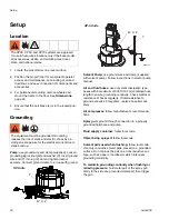
Grounding
Pump:
use ground wire and clamp (supplied). Loosen
grounding lug locknut (W) and washer (X). Insert ground
wire end (Y) into lug (Z) slot and tighten locknut
securely. Connect ground clamp to a true earth ground.
Solvent Pump:
use ground wire and clamp (supplied
with solvent pump). Follow instructions in solvent pump
manual.
Air and fluid hoses:
use only static dissipation type
hoses with a maximum of 500 ft (150 m) combined hose
length to ensure grounding continuity. Check electrical
resistance of hoses regularly. If total resistance to
ground exceeds 29 megohms, replace hose immedi-
ately.
Air compressor:
follow manufacturer’s recommenda-
tions.
Spray gun:
ground through connection to a properly
grounded fluid hose and pump.
Fluid supply container:
follow local code.
Object being sprayed:
follow local code.
Solvent pails used when flushing:
follow local code.
Use only conductive metal pails, placed on a grounded
surface. Do not place the pail on a nonconductive sur-
face, such as paper or cardboard, which interrupts
grounding continuity.
To maintain grounding continuity when flushing or
relieving pressure:
hold metal part of the spray gun
firmly to the side of a grounded metal pail, then trigger
the gun.
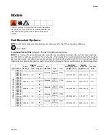
The XP35, XP50, and XP70 systems are approved
for use in hazardous locations only if the base model,
all accessories, all kits, and all wiring meet local,
state, and national codes.
The equipment must be grounded. Grounding
reduces the risk of static and electric shock by pro-
viding an escape wire for the electrical current due to
static build up.
Y
W, X, Z
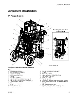
XP Units
WLD
Y
W, X, Z
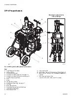
XP-h Units
Summary of Contents for XP-h
Page 45: ...Repair 3A0420V 45 ...
Page 69: ...Dimensions 3A0420V 69 ...


