background image

Warnings 

6

3A7939A

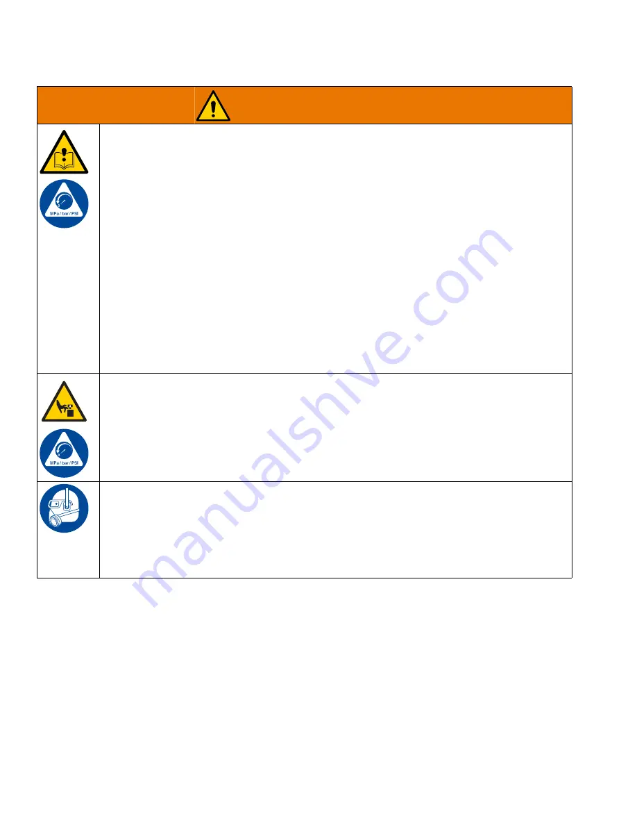
EQUIPMENT MISUSE HAZARD

Misuse can cause death or serious injury.

Do not operate or spray near children. Keep children away from equipment at all times. 

Do not operate the unit when fatigued or under the influence of drugs or alcohol.

Do not exceed the maximum working pressure or temperature rating of the lowest rated system 
component. See 

Technical Specifications

 in all equipment manuals.

Use disinfectants that are compatible with equipment wetted parts. See 

Technical Specifications


in all equipment manuals. Read disinfectant manufacturer’s warnings. For complete information 
about your disinfectant, request Safety Data Sheets (SDSs) from distributor or retailer.

Do not leave the work area while equipment is energized or under pressure.

Turn off all equipment and follow the 

Pressure Relief Procedure

 when equipment is not in use.

Check equipment daily. Repair or replace worn or damaged parts immediately with genuine 
manufacturer’s replacement parts only.

Do not alter or modify equipment. Alterations or modifications may void agency approvals and 
create safety hazards.

Make sure all equipment is rated and approved for the environment in which you are using it.

Use equipment only for its intended purpose. Call your distributor for information.

Route hoses and cables away from traffic areas, sharp edges, moving parts, and hot surfaces.

Do not kink or over bend hoses or use hoses to pull equipment.

Comply with all applicable safety regulations.

MOVING PARTS HAZARD

Moving parts can pinch, cut or amputate fingers and other body parts.

Keep clear of moving parts.

Do not operate equipment with protective guards or covers removed.

Equipment can start without warning. Before checking, moving, or servicing equipment, follow the 

Pressure Relief Procedure

 and disconnect all power sources.

PERSONAL PROTECTIVE EQUIPMENT

Wear appropriate protective equipment when in the work area to help prevent serious injury, 
including eye injury, burns, hearing loss, and inhalation of disinfectant chemical mists and vapors. 
Protective equipment includes but is not limited to:

• Protective eye-wear, and hearing protection. 
• Appropriate respirators, protective clothing, and gloves. 
• All protective equipment specified by the disinfectant manufacturer.

WARNING

Summary of Contents for SaniSpray HP 750

Page 1: ...Read all warnings and instructions in this manual in related manuals and on the unit before using the equipment Be familiar with the controls and the proper usage of the equipment Save these instructions Important Safety Instructions WARNING CHEMICAL HAZARD To prevent serious injury Follow all directions and requirements on disinfectant label It is a violation of federal law to use an EPA approved...

Page 2: ...tenance 24 Cart Maintenance 24 Troubleshooting 25 Error Code Troubleshooting 27 Repair 29 Disconnect the Pump 29 Reconnect the Pump 30 Replace the Rupture Disc Assembly 31 Parts 32 Sprayer 273215 Parts 32 4 Gun Manifold 273226 Parts 34 Dimensions 36 Technical Specifications 37 Recycling and Disposal 37 End of Product Life 37 California Proposition 65 37 Graco Warranty 38 Related Manuals Manuals ar...

Page 3: ...safety warnings in this manual NON ALCOHOL This type of disinfectant contains active ingredients such as aldehydes phenols quaternary ammonium compounds sodium hypochlorite bleach peroxyacetic acid hydrogen peroxide and hypochlorous acid Your sprayer is compatible with this type of disinfectant Before using your disinfectant sprayer read this manual for complete instructions on proper use and safe...

Page 4: ... the specific hazards of the disinfectants you are using Store and dispose of disinfectants according to instructions on disinfectant container labels FIRE AND EXPLOSION HAZARD Flammable fumes such as disinfectants in work area can ignite or explode Disinfectants flowing through the equipment can cause static sparking To help prevent fire and explosion Keep sprayer area well ventilated Keep a good...

Page 5: ...int spray tip at anyone or place any part of your body in front of tip For example do not try to stop leaks with any part of the body Do not spray without tip guard installed Engage trigger lock when not spraying Verify the trigger lock is functioning properly Do not stop or deflect leaks with your hand body glove or rag Equipment maintains pressure after power is shut off Do not leave equipment e...

Page 6: ...or modifications may void agency approvals and create safety hazards Make sure all equipment is rated and approved for the environment in which you are using it Use equipment only for its intended purpose Call your distributor for information Route hoses and cables away from traffic areas sharp edges moving parts and hot surfaces Do not kink or over bend hoses or use hoses to pull equipment Comply...

Page 7: ...tant Inlet D Packing Nut E Power Switch F Disinfectant Outlet G Tip and Tip Guard Assembly H Pressure Adjustment Knob J Outlet Check Valve L Status Indicator Light LED M Rupture Disc P Oil Fill Cap vented S Junction Box T Hopper U Hopper Bracket V Airless Hose W Gun X 4 gun manifold Y Gun Extension Z Power Cord Ref Description ...

Page 8: ...infectants with alcohol active ingredients When you are using disinfectants with alcohol based active ingredients you must use conductive metal containers which are able to be grounded To ground metal supply and flushing containers use a grounding wire and clamp GW Graco part 244524 not supplied Do not place grounded metal containers on a non conductive surface such as paper or cardboard which int...

Page 9: ...rayer draws Undersized extension cords result in a drop in line voltage and loss of power and overheating Select the minimum cord wire gauge based on length according to the table below Make sure your extension cord is not damaged Install Vented Oil Cap Before Using Equipment The sprayer s motor gear box is shipped from the factory pre filled with oil The temporary unvented cap PX prevents oil lea...

Page 10: ...l it stops then push the knob in to lock 6 Turn the power switch E OFF Plug the power cord into a grounded outlet Flush Before Using the Sprayer Your sprayer s pump has been factory tested with lightweight oil A small amount of this oil is left in the pump to protect parts To avoid contaminating your disinfectant with oil flush the sprayer with warm soapy water before using it for the first time S...

Page 11: ...23 from hopper bracket 19 to cart bracket 18 5 Remove nuts 6 and bolts 23 from cart bracket 18 and remove the bracket from cart 1 Connect the Suction Tube 1 Install fitting 38 and elbow 39 to the pump 9 WL D 2 Connect the suction tube 70 coupler 72 feed tube 71 and strainer 73 to hose 33 3 Connect hose 33 to elbow 39 4 Proceed to Connect Hose s and Gun s on page 12 Connect the Hopper 1 Use nuts 6 ...

Page 12: ...illustration on page 13 WL D 2 4 gun and 8 gun setups Follow steps 3 7 one time for each 4 gun manifold If you are using an 8 gun setup you will have to perform these steps twice See the 8 Gun Setup illustration on page 14 3 Connect a 3 8 in airless hose 110 to elbow 44 4 Connect a 3 8 in airless hose 110 to the 4 gun manifold tee fitting 101 5 Connect a 1 4 in airless hose 111 to the outlet of ea...

Page 13: ...Setup 3A7939A 13 4 Gun Setup WL D ...

Page 14: ...Setup 14 3A7939A 8 Gun Setup WL D ...

Page 15: ... triggered individually or all at the same time NOTE Once the first gun has been triggered there will be a noticeable decrease in pressure but the remaining guns will still need to be triggered to relieve all pressure 7 Engage all trigger locks 8 If you suspect that a spray tip or hose is completely clogged or that pressure has not been fully relieved a VERY SLOWLY loosen the tip guard retaining n...

Page 16: ...n 1 Then work your way back towards the sprayer position 2 position 3 etc with each additional gun 7 Prime the hoses and guns either separately or all at once a Disengage the trigger lock of each gun being used b Trigger each gun into a grounded metal pail c Pull out the pressure adjustment knob H and turn it clockwise slowly to increase pressure until a steady stream flows from each gun d Release...

Page 17: ... are installed properly CC BB AA G 1 Follow the Pressure Relief Procedure on page 15 2 Use spray tip AA to align the gasket and seal BB with the tip guard CC 3 Insert the spray tip into the tip guard Verify that the spray tip is forward in the SPRAY position 4 Screw the tip guard assembly G onto the spray gun and tighten To avoid serious injury from skin injection do not put your hand in front of ...

Page 18: ...rs 10 Slowly increase pressure using the pressure adjustment knob H Set the knob to the minimum setting needed to produce the desired spray of disinfectant Push the knob in to lock 11 Adjust the spray gun distance from the surface and your hand speed to achieve the desired surface coverage Always refer to the disinfectant manufacturer s recommendations for an acceptable spray of disinfectant 12 Fl...

Page 19: ...ng the gun UNCLOG SPRAY 1 Release the trigger Engage the trigger lock Rotate the spray tip to the UNCLOG position Disengage the trigger lock Triggerthe gun into a groundedmetal pail to clear the clog 2 Engage the trigger lock Rotate the spray tip back to the SPRAY position Disengage the trigger lock and continue spraying To avoid injury never point the gun at your hand or into a rag ...

Page 20: ...r To flush disinfectants with alcohol active ingredients ground the pail according to Grounding on page 8 6 Turn the power switch E ON 7 Flush the hoses and guns a Open all ball valves that have been used to spray If using an 8 gun setup be sure to open any ball valves used on both 4 gun manifolds NOTE Guns used can be flushed all at once or they can be flushed one at a time If flushing one gun at...

Page 21: ...all valve furthest from sprayer position 1 for an additional 30 seconds after flushing the other hoses This will ensure there is no disinfectant left in the manifold NOTE Flush all hoses and guns used at any point during spraying even if you only opened the ball valve but did not spray the gun i Engage all trigger locks NOTE If using an 8 gun setup be sure to repeat steps to flush the hoses and gu...

Page 22: ...rayer or hoses Do not store the sprayer while it is under pressure Store the sprayer indoors Store with all hoses and guns connected to 4 gun manifold For overnight shutdown stop the pump at the bottom of its stroke to prevent damaging the pump rod and throat packings Disinfectant left in the sprayer will damage the equipment To avoid damage always completely flush the sprayer with warm soapy wate...

Page 23: ...urs of use After the break in period change the oil once a year 1 Follow the Pressure Relief Procedure on page 15 NOTICE NOTICE 2 Place a minimum 2 quart 1 9 liter container under the oil drain port Remove the oil drain plug and allow all oil to drain from the motor 3 Reinstall the oil drain plug Torque to 18 23 ft lb 25 30 N m 4 Position the sprayer on a level surface Fill until the oil level is ...

Page 24: ...l hoses and fitting connections for leaks Tighten all connections before each use 5 Check hoses for damage every time you spray Do not attempt to repair the hose if the hose jacket or fittings are damaged Replace all damaged parts Cart Maintenance Periodically lubricate the axle between points A and B with lightweight oil see below WL D Keep the cart clean by wiping up spills daily For overnight s...

Page 25: ... the pump Clogged disinfectant hose gun or spray tip Follow the Clear Tip Clog procedure on page 19 or clean the hose and gun Motor parts are worn or damaged Repair or replace the motor see your motor manual Disconnect the Pump see page 29 If the motor will not cycle and does not blink an error code then troubleshoot the motor or replace No pressure or flow Disinfectant is leaking from the rupture...

Page 26: ...nual Read the disinfectant manufacturer s recommendations Dirty worn or damaged spray gun Service the spray gun see your spray gun manual Motor does not turn over and LED is off Over voltage greater than 300 V Check the power supply No power to the control board Verify that the power supply is connected Check the junction box connections Motor does not turn over and LED is on Encoder fault Cycle p...

Page 27: ...mp has not moved any disinfectant for 30 minutes Standby Mode will be exited when Disinfectant starts to dispense and causes the pump to move OR The pressure control knob H is adjusted OR The power switch E is cycled OFF and ON Error Codes Table Blink Code Error Type Troubleshooting Steps 1 Alarm Pump Diving Pump diving is when the pump moves through the down stroke too rapidly A pressure imbalanc...

Page 28: ...co distributor or Tech Service for more information 9 Alarm Encoder Error Cycle power and check the status indicator L to see if the error is still active Verify that the internal connections are intact Contact your Graco distributor or Tech Service for more information 10 Alarm Software Versions Do Not Match Obtain software update token See your motor manual for the token part number and token in...

Page 29: ...ve position of the pump s disinfectant outlet to the motor If the motor does not require servicing leave it attached to its mounting 6 Unscrew the coupling nut 13 from the connecting rod adapter 11 Remove the coupling collars 12 do not lose or drop them 7 Hold the tie rod flats with a wrench to keep the rods 8 from turning Unscrew the nuts 10 Remove the pump 9 8 To service the pump refer to your p...

Page 30: ...mp 9 to the motor 4 be sure to match the relative position of the pump s disinfectant outlet to the motor WL D T S L D 5 Screw the nuts 10 onto the tie rods 8 and torque to 50 60 ft lb 68 81 N m 6 Screw the coupling nut 13 onto the connecting rod adapter 11 loosely Hold the connecting rod adapter flats with a wrench to keep from turning 7 Use an adjustable wrench to tighten the coupling nut 13 Tor...

Page 31: ...d unplug the power cord Z WL D WL D 2 Remove elbow 44 from rupture disc assembly 15 3 Remove rupture disc assembly 15 from fitting 17 4 Install new rupture disc assembly into fitting 17 Use compatible liquid thread sealant or PTFE tape on connection 5 Reinstall elbow 44 and position as shown in the image ...

Page 32: ...LR GH SUHVL GHVFRQHFWH WRGDV ODV IXHQWHV GH HQHUJ DQWHV GH UHDOL DU WDUHDV GH VHUYLFLR WQLFR R OLPSLH D 0 18 16758 21 6 12 5 63 7 5 67 9 57 1 38 2 6 21 5 6 21 6 5 9 6 0387 1 862 08 5 7 1 5 0 48 7HQLU KRUV GH SRUW GHV HQIDQWV 8WLOLVH XQLTXHPHQW SRXU SXOYLVHU OHV VXUIDFHV 1H SXOYLVH SDV GH SHUVRQQHV RX G DQLPDX 6XLYH WRXWHV OHV LQVWUXFWLRQV HW FRQGLWLRQV ILJXUDQW VXU OꏡWLTXHWWH GX GLQIHFWDQW 5LQFH D...

Page 33: ...er painted 1 20 113362 WHEEL semi pneumatic 2 21 154628 WASHER 2 22 113436 RING retaining 2 23 17V628 SCREW cap hex head 4 24 19B620 FITTING cam and groove sst 1 25 19B625 FITTING cam groove 1 5m 1 1 2 npt 1 26 124445 FITTING coupling 1 1 2 nptf ss 1 31 17E114 HOPPER weldment xtreme 1 33 214959 HOSE coupled 1 38 121239 BUSHING 1 5 x 1 npt reducer sst 1 39 121245 FITTING swivel 1 x 1 npt 1 40 10290...

Page 34: ...Parts 34 3A7939A 4 Gun Manifold 273226 Parts WL D ...

Page 35: ...08 SEALANT pipe sst 1 106 25R874 GUN SaniSpray hp 4 107 26B143 EXTENSION tip 15 in e n assy 4 108 25R880 KIT tip seat hp LP 617 LP 621 4 109 LP723 TIP spray LP 723 4 110 240797 HOSE coupled 3 8 in x 50 ft 1 111 223771 HOSE cpld 1 4 in x 100 ft 12 112 19Y494 HOSE cpld 1 8 in x 4 1 2 ft 4 113 121907 FITTING nipple hex 1 4 npt sst swv 8 114 LP631 TIP spray LP 631 4 Ref Part Description Qty ...

Page 36: ...Dimensions 36 3A7939A Dimensions Dimensions WL D B C A Ref A Height 50 0 in 1 27 m B Depth 30 0 in 0 76 m C Width 26 0 in 0 66 m ...

Page 37: ...oke Length 4 75 in 120 mm Maximum Continuous Cycle Rate 33 cycles per minute Maximum Tip Size 0 031 in Wetted Parts stainless steel PTFE acetal UHMWPE anodized aluminum fluoroelastomer urethane nylon Maximum Disinfectant Temperature 120 F 50 C Operating Temperature Range 23 to 120 F 5 to 50 C Input Voltage 200 240 VAC single phase 50 60 Hz Input Current 20 A maximum Minimum Recommended Generator S...

Page 38: ... incidental or consequential loss shall be available Any action for breach of warranty must be brought within two 2 years of the date of sale GRACO MAKES NO WARRANTY AND DISCLAIMS ALL IMPLIED WARRANTIES OF MERCHANTABILITY AND FITNESS FOR A PARTICULAR PURPOSE IN CONNECTION WITH ACCESSORIES EQUIPMENT MATERIALS OR COMPONENTS SOLD BUT NOT MANUFACTURED BY GRACO These items sold but not manufactured by ...

Reviews: