background image

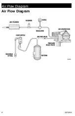
Air Flow Diagram 

8

3A7026A

Air Flow Diagram

Summary of Contents for RTX2000

Page 1: ...etro Flowswitch kits For professional use only Kit Part Number 17Z247 120V 19Y417 230V Important Safety Instructions Read all warnings and instructions in this manual and in the Operation and Parts manual 3A3258 before using the equipment Save all instructions Related Manuals 3A3258 Operation Parts ti27336a ...

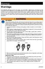
Page 2: ...ic shock When repair or replacement of the cord or plug is required do not connect the grounding wire to either flat blade terminal The wire with insulation having an outer surface that is green with or without yellow stripes is the grounding wire Check with a qualified electrician or serviceman when the grounding instructions are not completely understood or when in doubt as to whether the produc...

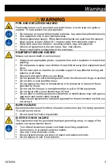
Page 3: ...ng and balance at all times Stay alert and watch what you are doing Do not operate the unit when fatigued or under the influence of drugs or alcohol Do not kink or over bend the hose Do not expose the hose to temperatures or to pressures in excess of those specified by Graco Do not use the hose as a strength member to pull or lift the equipment Do not spray with a hose shorter than 25 feet Do not ...

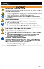
Page 4: ...ment follow the Pressure Relief Procedure and disconnect all power sources PLASTIC PARTS CLEANING SOLVENT HAZARD Many cleaning solvents can degrade plastic parts and cause them to fail which could cause serious injury or property damage Use only compatible solvents to clean plastic structural or pressure containing parts See Technical Specifications in all equipment manuals for materials of constr...

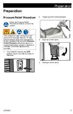
Page 5: ...issipate 2 Trigger gun into material hopper 3 Open air control valve 4 Open gun prime valve This equipment stays pressurized until pressure is manually relieved To help prevent serious injury from pressurized fluid or splashed fluid follow the Pressure Relief Procedure whenever sprayer is stopped and before sprayer is cleaned or checked and before equipment is serviced ti27340a ti27339a ti27341a ...

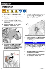
Page 6: ... disconnected as they will attach to the new assembly 6 Fasten the new flowswitch assembly to the unit using the provided bolts as shown below Torque each bolt to 27 32 in lb 3 1 3 6 N m 7 Hook up the flowswitch assembly to the air and electrical system following the provided diagrams 8 Secure wiring away from moving parts using the provided zip ties 9 Assemble the shrouds toolbox handle and hoppe...

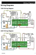
Page 7: ...Wiring Diagrams 3A7026A 7 Wiring Diagrams 120V Wiring Diagram 230V Wiring Diagram ...

Page 8: ...Air Flow Diagram 8 3A7026A Air Flow Diagram ...

Page 9: ...Notes 3A7026A 9 Notes ...

Page 10: ...pliance WARNING This product can expose you to chemicals known to the State of California to cause cancer and birth defects or other reproductive harm For more information go to www P65Warnings ca gov California Proposition 65 ...

Page 11: ...s of parts labor and transportation THIS WARRANTY IS EXCLUSIVE AND IS IN LIEU OF ANY OTHER WARRANTIES EXPRESS OR IMPLIED INCLUDING BUT NOT LIMITED TO WARRANTY OF MERCHANTABILITY OR WARRANTY OF FITNESS FOR A PARTICULAR PURPOSE Graco s sole obligation and buyer s sole remedy for any breach of warranty shall be as set forth above The buyer agrees that no other remedy including but not limited to inci...

Page 12: ...olis International Offices Belgium China Japan Korea GRACO INC AND SUBSIDIARIES P O BOX 1441 MINNEAPOLIS MN 55440 1441 USA Copyright 2019 Graco Inc All Graco manufacturing locations are registered to ISO 9001 www graco com Revision A October 2019 Graco Information For the latest information about Graco products visit www graco com For patent information see www graco com patents TO PLACE AN ORDER ...

Reviews: