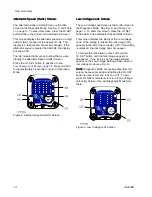
Gun Overview
Controls,
Controls,
Controls, Indicators,
Indicators,
Indicators, and
and
and Components
Components
Components
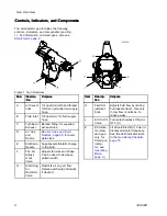
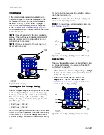
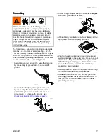
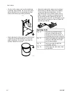
The electrostatic gun includes the following
controls, indicators, and components (see Fig.
1). For information on Smart guns, also see
Smart Guns, page 9
.
Figure 1 Gun Overview
Item
Item
Item
Descrip-
Descrip-
Descrip-
tion
tion
tion
Purpose
Purpose
Purpose
A
Air Swivel
Inlet
1/4 npsm(m) left-hand thread,
for Graco grounded air supply
hose.
B
Fluid Inlet
3/8 npsm(m), for fluid supply
hose.
C
Turbine Air
Exhaust
Barbed fitting, for supplied
exhaust tube.
D
Air Cap
and
Nozzle
See
Air Caps and Fluid
Nozzles, page 68
, for avail-
able sizes.
E
Electrode
Needle
Supplies electrostatic charge
to the fluid.
F
Fan Air
Adjust-
ment
Valve
Adjusts fan size and shape.
Can be used to decrease
pattern width.
G
Atomizing
Air
Restrictor
Valve
Restricts air cap air flow.
Replace with plug (included)
if desired.
Item
Item
Item
Descrip-
Descrip-
Descrip-
tion
tion
tion
Purpose
Purpose
Purpose
H
Fluid Ad-
justment
Knob
Adjusts fluid flow by limiting
fluid needle travel. Use only
in low flow conditions, to
reduce wear.
J
ES On-Off
Valve
Turns electrostatics ON (I) or
OFF (O).
K
ES Indica-
tor (stan-
dard gun
only; for
Smart gun
indica-
tor, see
Operating
Mode,
page 9
)
Lit when ES is ON (I). Color in-
dicates alternator frequency.
See the LED indicator table
in the
Gun Setup Checklist,
page 18
.
8
3A2494D


