background image

10    308393

Installation

Install the Gun Washer

WARNING

FIRE HAZARD
To prevent hazardous concentrations of
flammable and/or toxic vapors, the gun
washer must be installed in a properly

ventilated paint mixing room or spray booth. Never
operate the gun washer unless ventilation fans are
operating.

Check and follow all the National, State and Local
codes regarding ventilation requirements.

Make sure the gun washer is standing on a level, solid
surface.

Grounding

WARNING

FIRE AND EXPLOSION HAZARD
Improper grounding can cause a
hazardous condition and result in fire or
explosion and serious injury. Ground the
gun washer and all other equipment
used or located in the gun washer area.
Check your local electrical code for

detailed grounding instructions for your area and
type of equipment. Also read the section FIRE
AND EXPLOSION HAZARD
, on page 4.

1.

Ground the gun washer and its pump by connect-
ing the clamp end (A) of the gun washer’s 15 ft.
(4.6 m) ground wire (B) to a true earth ground (C).
See Fig. 2.

2.

Use only grounded air and fluid hoses with a maxi-
mum of 500 ft. (150 m) combined hose length to
ensure grounding continuity.

3.

Ground the air compressor according to manufac-
turer’s recommendations.

4.

Ground all solvent pails used when flushing and
draining according to local code. Use only metal
pails, which are conductive. Do not place the pail
on a non-conductive surface, such as paper or
cardboard, which interrupts the grounding continu-
ity.

Connect the Air Line

1.

Install an air pressure regulator (D) on the gun
washer air supply line to control air pressure to the
gun washer. See Fig. 2.

2.

Install a bleed-type master air valve  (E) upstream
and within easy reach of the gun washer to relieve
air trapped between this valve and the pump after
the air is shut off.

WARNING

PRESSURIZED EQUIPMENT HAZARD
The bleed-type master air valve (E) is required in
your system to relieve air trapped between this
valve and the pump after the air is shut off.
Trapped air can cause the pump to cycle unexpect-
edly, which could result in serious injury, including
splashing in the eyes or on the skin.
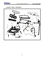
3.

Install a 1/4 in. npt male coupler (F), that is com-
patible with the quick disconnect of your air supply
line, into the air inlet adapter (G). See Fig. 1.

4.

Connect the air line (H) to the coupler (F).

Fig. 1

03302

F

G

Summary of Contents for PRO-WASH 112634

Page 1: ...raco Inc is registered to I S EN ISO 9001 PRO WASHt Gun Washer With Huskyt 307 Pump 100 psi 0 7 MPa 7 bar Maximum Working Pressure 308393J Read warnings and instructions See page 2 for List of Models...

Page 2: ...are 17 Parts Model 112634 20 Model 112635 22 Model 117438 24 Warranty 26 Graco Information 26 Symbols Warning Symbol WARNING This symbol alerts you to the possibility of serious injury or death if you...

Page 3: ...ving parts and hot surfaces Do not expose Graco hoses to temperatures above 180 F 82 C or below 40 F 40 C Do not use the hoses to pull the equipment Do not move pressurized equipment Use fluids or sol...

Page 4: ...o not flush an electrostatic gun with the electrostatics ON OFF lever in the ON position If there is any static sparking while using the equipment stop operation immediately Identify and correct the p...

Page 5: ...air less guns Spray nozzle 512799 2 Siphon pressure cups 112635 Long gun support 512800 2 Pressure feed air spray HVLP guns Hose wash Pot wash capability order kit 236906 Short gun support 112847 1 S...

Page 6: ...ay and airless conventional guns 512800 Long gun support 112847 Short gun support thin stem 512835 Fluid inlet adapter 512802 Wire trigger lock 236906 Pressure pots and other paint containers see page...

Page 7: ...m Tank Capacity 5 gallons 19 liters Air Inlet 1 4 npt f Fluid Drain Valve 1 in npt m Approximate Dry Weight Model 112634 63 lbs 28 6 kg Model 112635 65 lbs 29 5 kg Model 117438 86 lbs 39 kg Wetted Par...

Page 8: ...del 117438 B A C D E B A C D E Model Measurements inches mm A B with lid closed B with lid opened C D E 112634 and 112635 20 75 527 42 25 1073 61 00 1549 20 50 521 16 25 413 25 12 638 117438 19 25 489...

Page 9: ...308393 9 Notes...

Page 10: ...maxi mum of 500 ft 150 m combined hose length to ensure grounding continuity 3 Ground the air compressor according to manufac turer s recommendations 4 Ground all solvent pails used when flushing and...

Page 11: ...308393 11 Installation Fig 2 Typical Installation and Grounding 03301 D E H A B C F...

Page 12: ...recommendations Pressure Relief Procedure WARNING PRESSURIZED EQUIPMENT HAZARD The system pressure must be manually relieved to prevent the system from starting accidentally To reduce the risk of an i...

Page 13: ...un fluid inlet over the long gun support as shown in Fig 3 Electrostatic Guns The PRO Wash gun washer is approved to clean the Graco PRO 3500 PRO 4500 PRO AA4500 PRO Xs2 PRO Xs3 PRO Xs4 and PRO Xs4 AA...

Page 14: ...dth of the container the pressure washers can clean are shown below See the manual supplied with the kit Manual 308414 to install and use this option See page 5 for kit description Container Gun Washe...

Page 15: ...he gun supports and spray nozzles Model 117438 Using the Hose Wash 1 Remove the brass plugs from the Hose Wash Bulkhead See Fig 5 Fig 5 Hose Wash Bulkhead Hose Wash Bulkhead 2 Install a female fluid q...

Page 16: ...ge the setting on the Husky pump s air filter regulator as this will damage the regulator 2 Make sure all adapter chains and cables are inside the gun washer tank 3 If one or more of the gun mounts is...

Page 17: ...ughly clean the gun washer filter item 12 in the Parts Drawings with a brush 5 Change the solvent completely when it is no longer thoroughly cleaning the painting equipment If the gun washer is being...

Page 18: ...Make sure the gun washer is properly grounded before operating it again Check your local electrical code for detailed grounding instructions for your area and type of equipment If electrical continuit...

Page 19: ...308393 19 Notes...

Page 20: ...34 13 12 2 27 Ref A 5 15 16 8 6 28 03309 Reference Fluid Manifold Detail 26 1 4 28 Pump Ground Bar Detail E E A B A E C D E E E D B C NOTE The circled letters indicate the continuation points of illus...

Page 21: ...ng 1 16 103538 CLAMP grounding 1 17 512799 NOZZLE spray plastic 14 18 GUN SUPPORT long brass 1 Ref No Part No Description Qty 19 GUN SUPPORT short brass 1 20 TRIGGER LOCK wire stainless steel 2 21 ADA...

Page 22: ...5 03310 13 2 27 Ref A 5 15 16 8 6 28 26 1 28 14 Reference Fluid Manifold Detail Pump Ground Bar Detail E E A B A E E E E D B C NOTE The circled letters indicate the continuation points of illustra tio...

Page 23: ...IRE grounding 1 16 103538 CLAMP grounding 1 17 512799 NOZZLE spray plastic 13 18 GUN SUPPORT long brass 2 Ref No Part No Description Qty 19 GUN SUPPORT short brass 1 20 TRIGGER LOCK wire stainless ste...

Page 24: ...24 308393 Parts for Model 117438 29 32 12 37 39 36 23 35 38 6 14 E E 15 16 28 Pump Ground Bar Detail E E...

Page 25: ...2 TRIGGER LOCK wire stainless steel 3 21 512835 ADAPTER gun fluid inlet brass 3 23 513284 GASKET lid 1 Ref No Part No Description Qty 28 513049 JUMPER ground 4 29 117415 KNOB timer 1 35 117422 FILTER...

Page 26: ...cluding but not limited to incidental or consequential damages for lost profits lost sales injury to person or property or any other incidental or consequential loss shall be available Any action for...

Reviews: