Installation
309457G
11
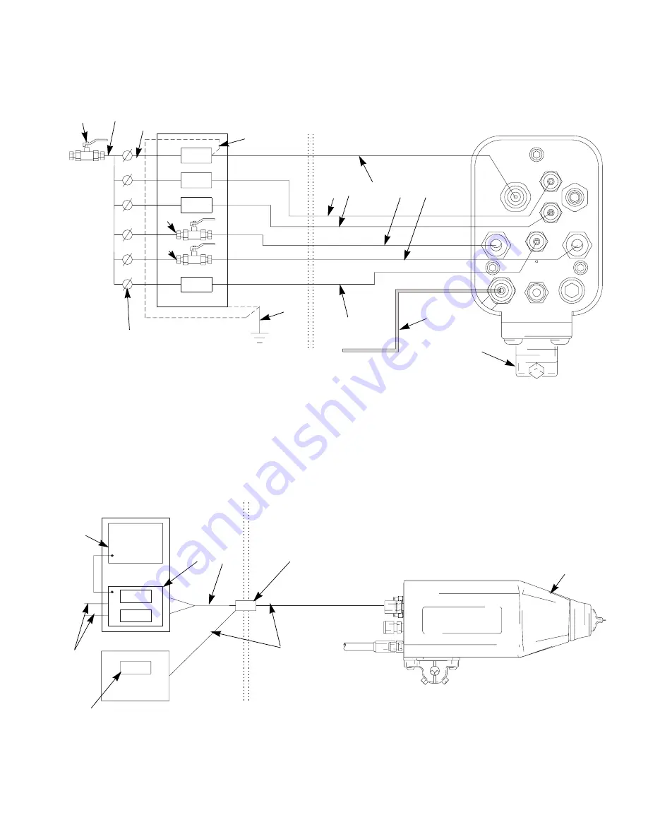
Fig. 2. Typical Installation
Fig. 3. Optional Fiber Optic Connection to Voltage Display Module
TI1801A
A
B
C
D
E
F
J
K
M
N
G
NOTE:
* The turbine air supply (TA) must be electrically interlocked with the spray booth ventilation fans to prevent
the power supply from operating without ventilating fans on.
Non-Hazardous
Hazardous Area
Y
W
P1
CYL
A2
A1
KV2
TA
K
K
See *
above
K
X
KV1
L
L
L
Manifold Back
KV
mA
85.0 KV
TI1797A
Q
T
NOTE:
** A maximum of two splices with a total of 108 ft (33 m) of cable can be used. For the strongest
light signals, use a minimum number of bulkhead splices. See Accessories on page 57.
Non-Hazardous
Hazardous Area
H
U**
R
P
S
V**
Do not use the Display Module readings to determine if your
system is discharged. The display modules only display the
system voltage while the gun’s power supply is operating. Fol-
low the Fluid Voltage Discharge and Grounding Procedure
on page 21 to ensure the system is discharged.
Summary of Contents for PRO Auto Xs
Page 51: ...Repair 309457G 51 ...


