background image

INSTRUCTIONS–PARTS LIST

308–385

Rev. C

Supersedes A

and PCN B

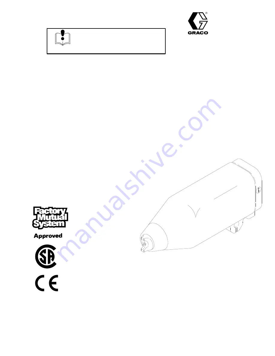
AUTOMATIC ELECTROSTATIC

Model PRO 5500sc

Air Spray Gun

100 psi (7 bar) Maximum Working Pressure

For use with Class 

, Group D paint  spray materials

U.S. PATENT NO. 4,290,091; 4,219,865; 4,497,447; 4,462,061; 4,660,774; 
5,063,350; 5,073,709; 5,080,289; 5,093,625; 5,289,977 
Patented 1986, 1987 Canada 
Brevete 1986, 1987 
U.K. PATENT NO. 2,147,158; 2,142,559B; 2,140,327–B 
Other Foreign Patents Pending

Part No. 236–683, Series A

Complete Standard PRO 5500sc Spray Gun: includes
spray gun, shroud, manifold, and mounting bracket

Part No. 236–684, Series A

Complete PRO 5500sc Recirculating Spray Gun: same
as part no. 236–683 spray gun only with part no.
236–851 recirculation kit installed

GRACO INC.   P.O. BOX 1441  MINNEAPOLIS, MN  55440–1441

COPYRIGHT 1994 GRACO INC.

This manual contains important 
warnings and information. 
READ AND RETAIN FOR REFERENCE

INSTRUCTIONS

Summary of Contents for PRO 5500sc

Page 1: ...Brevete 1986 1987 U K PATENT NO 2 147 158 2 142 559B 2 140 327 B Other Foreign Patents Pending Part No 236 683 Series A Complete Standard PRO 5500sc Spray Gun includes spray gun shroud manifold and mo...

Page 2: ...Notes...

Page 3: ...eaning 20 Clean the Air Cap and Fluid Nozzle 22 Check for Fluid Leakage 23 Troubleshooting Spray Pattern Troubleshooting 24 Gun Operation Troubleshooting 25 Electrical Troubleshooting 26 Electrical Te...

Page 4: ...0 F 38 C Do not flush the system with the gun electrostatics turned on Do not turn on the gun electrostatics until all solvent is removed from the system Use only non sparking tools to clean residue f...

Page 5: ...with the equipment wetted parts See the Technical Data section of all the equipment manuals Read the fluid manufacturer s warnings Route the hoses away from traffic areas sharp edges moving parts and...

Page 6: ...ep contaminants out and helps keep the gun clean Switching to the Higher or Lower kV Setting The gun s full high voltage setting is 85 kilovolts The gun s spraying voltage can be reduced by switching...

Page 7: ...D Shroud E Mounting Bracket F Manifold G Turbine H Power Supply J Electrode Manifold Markings A1 Atomization Air Inlet Fitting A2 Fan Air Inlet Fitting CYL Cylinder Air Inlet Fitting EXH Shroud Exhaus...

Page 8: ...s Area BASIC SYSTEM SYSTEM OPTIONS S Spraying Voltage Display Module kV A Non Hazardous Area Hazardous Area S Air Pilot Fluid Regulator S Dump Valve Fig 1 Fig 2 TA A2 A1 CYL A B K K J G H P1 E F M N C...

Page 9: ...D Installing and servicing this equipment requires access to parts which could cause an electric shock or other serious injury if the work is not performed properly D Do not install or service this eq...

Page 10: ...must have a quick exhaust port PRESSURIZED EQUIPMENT HAZARD Trapped air can cause the gun to spray unexpectedly which could result in a serious injury including splashing in the eyes or on the skin Th...

Page 11: ...ive nylon core urethane outer Grey Hose more flexible less durable than black hose modified semi conductive polyamide core urethane cover Red Hose conductive SST wire braid for grounding polyure thane...

Page 12: ...12 308 385 Notes...

Page 13: ...it is recommended that you install the fiber optic lens kit as described at right NOTE Most of the fiber optic light transmission loss occurs at the bulkhead splices For the strongest light signals u...

Page 14: ...r s recommendations 3 PRO 5500sc Electrostatic Air Spray Gun ground the gun by connecting the Graco Electrically Con ductive Air Hose and connecting the air hose ground wire to a true earth ground Che...

Page 15: ...ure the turbine air hose B is connected and the hose ground wire is connected to a true earth ground 3 The air and fluid supplies to the gun must be turned off and the fluid hose must not have any flu...

Page 16: ...ubing and hoses at the back of the manifold See Fig 11 2 Route the exhaust tube YY outside the cover This enables you to monitor the exhaust tube for the presence of any paint or solvent See Check for...

Page 17: ...trostatic air spray system as instructed in this manual ____ 2 Be sure all the operators are trained how to properly relieve system pressure as instructed at left ____ 3 Be sure the warning sign provi...

Page 18: ...uid line pressure regulator Refer to instruction manual 307 803 to set the fluid pressure for various fluid flows according to the size of the fluid nozzle being used 4 Use the air pressure regulator...

Page 19: ...happen with all resistive electrostatic guns See Electrical Troubleshooting on page 26 to cor rect voltage problems Activating the kV Switch Apply a minimum of 50 psi 3 5 bar air pressure to the kV s...

Page 20: ...solvents can cause the gun to malfunction Methylene chloride is not recommended as a flushing or cleaning solvent with this gun as it will damage nylon components Fluid in the air passages could caus...

Page 21: ...p if they are damaged See Clean the Air Cap and Fluid Nozzle page 22 Check the electrode wire straighten it if it is bent and replace it if it is broken or damaged See Elec trode Needle Replacement pa...

Page 22: ...r cap in suitable solvent and wipe it clean CAUTION 03511 Do not use metal tools to clean the air cap or fluid nozzle holes as this could scratch them and make sure the electrode wire is not damaged S...

Page 23: ...op spraying and whenever you are instructed to relieve the pres sure WARNING During operation periodically check the manifold exhaust tube YY and both ends of the gun shroud ZZ for the presence of flu...

Page 24: ...lose to the fluid needle The fluid seat is worn Clean or replace the air cap see page 22 Reposition the actuator arm see page 34 Replace the fluid nozzle and or electrode needle see page 30 and 31 The...

Page 25: ...t of position Check the fluid supply add fluid if necessary Clean the fluid nozzle see page 22 Replace the fluid nozzle see page 30 Check the cylinder air check the piston u cup see page 33 Check the...

Page 26: ...heck the possible causes listed below Check the air supply to the gun Check the gun resistance see page 27 Clean the fluid rod cavity replace the packing see page 32 Be sure the plug is in place on th...

Page 27: ...t as instructed on page 29 before performing the electrical tests FIRE EXPLOSION AND ELECTRIC SHOCK HAZARD To reduce the risk of sparking which could cause a fire explosion or electric shock and resul...

Page 28: ...edle contact ring T You may have to press down on the contact ring S in several places to get a good reading The resistance should be 21 to 29 megohms If the resistance is correct make sure the metal...

Page 29: ...ts PRESSURIZED EQUIPMENT To reduce the risk of a serious injury follow the Pressure Relief Procedure on page 17 when you stop spraying be fore servicing the gun and whenever you are instructed to reli...

Page 30: ...zle 14 with the hex key wrench 83 See Fig 21 FIRE EXPLOSION AND ELECTRIC SHOCK HAZARD The resistor stud contact ring S is a conductive contact ring not a sealing o ring See Fig 20 To reduce the risk o...

Page 31: ...39 Electrode Needle Replacement 1 Prepare the gun for service as instructed on page 29 2 Remove the air cap fluid nozzle and resistor stud as instructed on page 30 Remove the gun shroud 3 Unscrew and...

Page 32: ...cking rod assembly 28 with the 9 mm hex nut driver 79 See Fig 23 6 Clean all the parts and check them for wear or damage Replace the parts if necessary Before installing the fluid packing rod assembly...

Page 33: ...then check the drag on the fluid rod See Fig 23 14 Make sure the spring 11 is installed on the nut U as shown in Fig 24 15 Install the electrode needle fluid nozzle and resis tor stud as instructed o...

Page 34: ...fan and atomizing air pressure U cup 23f Cylinder Air Seal If the air leaks from the small vent hole in the back of the manifold when the gun is triggered replace the u cup Fig 27 23a 23c 23b 23f Fan...

Page 35: ...TE The fluid nozzle 14 must be in place when removing or installing the jam nut and actuator arm 5 Loosen the three screws 24 with the ball end wrench 77 not shown See Fig 29 6 Hold the gun body 29 wi...

Page 36: ...If nec essary replace the power supply 5 Before installing the power supply inspect the seal 27d for any damage or swelling replace the seal if necessary Make sure the gaskets and pads 27a 27e are in...

Page 37: ...y from the power supply 27 until the wire connector V disengages See Fig 31 4 Use an ohmmeter to test the turbine alternator coil Measure the resistance between the two outer ter minals of the 3 wire...

Page 38: ...o 18 in lbs 2 NSm maximum about a half turn past snug using the wrench 77 supplied 4 Install the fluid tube back into the fluid fitting 4 and tighten the nut 43 5 Install and adjust the actuator arm 1...

Page 39: ...101 See Fig 33 Inspect the parts for damage and replace them as needed 2 Secure the gun B to the manifold 101 by tight ening the three screws 106 with the ball end wrench 77 not shown 3 Secure the gu...

Page 40: ...2 3 9 1 2 27e 27b 25a 25 25b 30 27c 27 27d 27a 20 24 26 22 18 17 03227 31 REF 33 23g 75 See page 45 to order parts 33 35 34 7 6 21 46 19 36 11 4 5 29 Item 23 includes 23a 23g Item 25 includes 25a 25b...

Page 41: ...b 185 124 S CUSHION 1 26 223 940 BARREL gun 1 Ref No Part No Description Qty 27 224 093 POWER SUPPLY ASSY 85 kV Includes items 27a 27e 1 27a 186 840 S GASKET power supply 1 27b 185 099 S PAD 1 27c 185...

Page 42: ...9 1 2 27e 27b 25a 25 25b 30 27c 27 27d 27a 20 24 26 22 18 17 31 REF 33 23g 75 See page 45 to order parts 33 35 34 7 6 21 46 19 36 11 4 5 29 Item 23 includes 23a 23g Item 25 includes 25a 25b Item 27 in...

Page 43: ...HION 1 26 223 940 BARREL gun 1 Ref No Part No Description Qty 27 224 093 POWER SUPPLY ASSY 85 kV Includes items 27a 27e 1 27a 186 840 S GASKET power supply 1 27b 185 099 S PAD 1 27c 185 145 S PAD 1 27...

Page 44: ...05 Tighten the fitting until the hex bottoms against the manifold This fitting 113 has left hand threads Install the kV cap 111 flush to the outside surface Concave side of the disk 114 faces toward t...

Page 45: ...ING 1 123 111 316 O RING fluoroelastomer 1 These parts are included in Fluid Seal Repair Kit 236 828 which may be purchased separately These parts are included in Air Seal Repair Kit 236 827 which may...

Page 46: ...1 meter from the air cap Sound power was measured per ISO 3744 1981 Vitonr and Kalrezr Loctiter is a registered trademark of the Loctite Corporation Chemrazr is a registered trademark of the Green Tw...

Page 47: ...Notes...

Page 48: ...nt will be returned to the original purchaser transportation prepaid If inspection of the equipment does not disclose any defect in material or workmanship repairs will be made at a reasonable charge...

Reviews: