background image

Installation 

10

3A5266G

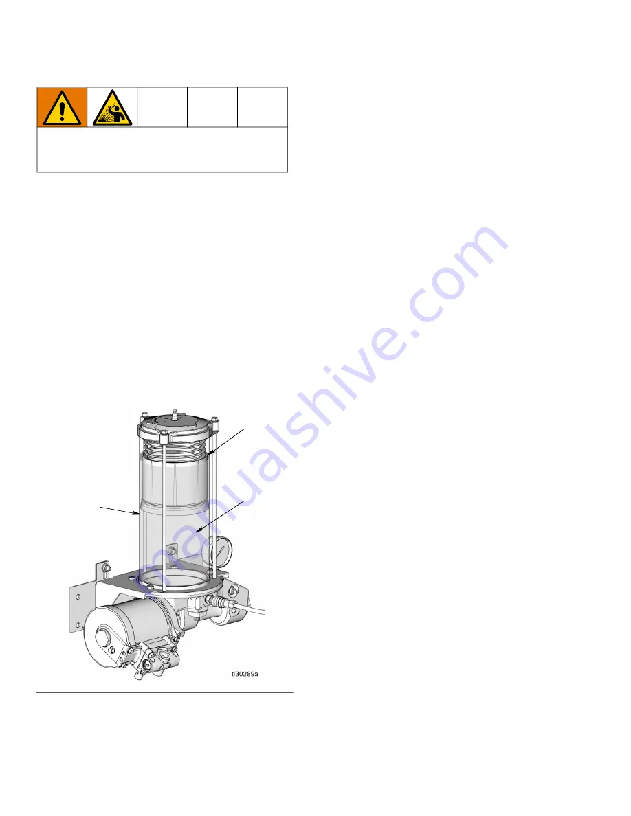
3. Slowly dispense grease from the fill pump into the 

reservoir until the grease in the reservoir lifts the fol

-

lower plate (45) above the reservoir vent hole (vh) 

and air is expended from under the follower plate 

(F

IG

. 9). A small amount of grease may come out of 

the vent hole at this time. 

Care must be taken not to overfill the reservoir. An 

over filled reservoir will vent the excess grease out 

of the vent hole (vh) until enough grease is expelled 

for the follower plate (45) to block the vent hole. 

Overfilling the reservoir could also cause the reser

-

voir to rupture due to over-pressurization.

NOTE:

 The vent hole (

vh

)

 is located toward the back 

right side of the reservoir and cannot be seen in F

IG

. 9

The approximate location of the vent hole is identified 

as 

vh 

in the illustration.

4. Disconnect the fill pump from the fill stud (26, F

IG

8).

5. Secure dust cap (42) over fill stud (26) (F

IG

. 8).

Priming

Refer to F

IG

. 1 and F

IG

. 2, pages and 6, for the follow

-

ing instructions.

NOTE: 

• Prime the pump before connecting the outlet to 

supply line (G).

• Before priming the pump, the reservoir must be 

filled with lubricant (see Fill Reservoir instructions, 

page 8).

Run the pump until lubricant, free of air, comes out of 

the pump outlet (E). It may take up to 20 pump strokes 

to expel the air from the pump and deliver a continuous 

flow of lubricant. This will depend on the viscosity of the 

lubricant and temperature.

Supply Lines

1. Run the pump until the oil (

ol

), free of air, comes out 

of the pump outlet (E). Connect the supply line (G) 

to the pump outlet (E).

2. If there are multiple pumps on the air line, close the 

air regulators and bleed-type master air valves to all 

but one of the pumps. If there is only one pump, 

open its air regulator and bleed-type master air 

valve.

3. Open the master air valve from the compressor.

4. Set the air pressure to each pump at the lowest 

pressure needed to get the desired results. 

Feeder Lines 

Fill each feeder line with lubricant prior to connecting 

feeder lines to the injector outlet or divider valve. 

Injectors

1. Check each injector for proper operation. The injec

-

tor stem should move when lubricant is discharged.

2. Adjust the injector output if needed to ensure that 

the output volume discharged is sufficient.

Over-pressurization can result in equipment rupture 

and serious injury. Fill slowly to avoid over pressuriz

-

ing reservoir.

F

IG

. 9

45

(vh)

(gr)

Summary of Contents for LubePro A4000

Page 1: ...corrosive and non abrasive lubricants only For professional use only Models Page 2 4000 psi 27 58 MPa 275 8 bar Maximum Working Pressure Related Manuals 406900 Air Motor Repair Kit Important Safety I...

Page 2: ...arts Oil Models 20 Parts Oil Models 21 Repair Air Valve 22 Replace Pilot Valves 24 Repair Air Motor 24 Air Motor Installation 27 Air Motor Parts 28 Air Motor Parts 29 Complete Air Valve Replacement Ki...

Page 3: ...utlet Do not stop or deflect leaks with your hand body glove or rag Follow the Pressure Relief Procedure when you stop dispensing and before cleaning checking or servicing equipment Tighten all fluid...

Page 4: ...dure when equipment is not in use Check equipment daily Repair or replace worn or damaged parts immediately with genuine man ufacturer s replacement parts only Do not alter or modify equipment Alterat...

Page 5: ...ir Lubricator C Air solenoid valve 3 way D Pump Module E Pump Outlet F Bleed type Master Air Valve required G High Pressure Lubricant Supply Lines H Injector J Lubricator Controller K Pump Reservoir L...

Page 6: ...Air Filter B2 Air Regulator B3 Air Lubricator C Air Solenoid Valve 3 way D Pump Module E Pump Outlet F Bleed type Master Air Valve required G High Pressure Lubricant Supply Lines J Lubricator Controll...

Page 7: ...39 Secure pump bracket to wall bracket using wash ers 60 and nuts 44 Low Level For models equipped with a low level switch connec tion is made to pins 1 and 2 for normally closed opera tion or pins 1...

Page 8: ...ratio of the pump 40 1 by the air pressure shown on the regulator gauge i e 40 psi x 40 1600 psi 2 75 bar x 40 110 bar 0 27 MPa x 40 10 8 MPa 8 Limit the air pressure to the pump so that no air line...

Page 9: ...it thoroughly c If removed in Step b install filter 33 prior to adding lubricant 2 Slowly add oil ol until reservoir is filled to capacity FIG 7 Take care to not fill reservoir too quickly and overfl...

Page 10: ...ir must be filled with lubricant see Fill Reservoir instructions page 8 Run the pump until lubricant free of air comes out of the pump outlet E It may take up to 20 pump strokes to expel the air from...

Page 11: ...oint or counter clockwise to decrease the pressure relief point Whenever the valve is set adjusted after the set point is found it is import ant to ensure that the valve is not bottomed out and there...

Page 12: ...c vent valve an elec trical signal to the vent valve is required to build pressure The same signal can be used to cycle the air valve and close the vent valve Low Level Switch Models 17P751 grease and...

Page 13: ...eck piping for leaks If a leak is detected repair or replace piping 2 Check injectors for leaks If a leak is detected repair or replace injector 3 If the pressure relief valve is set below the injecto...

Page 14: ...pump base 2 Remove air motor from pump base FIG 15 Pump Lower Disassembly 1 Follow the Remove Air Motor instructions to remove the air motor 1 from the pump base 2 if required OR Shut down pump page...

Page 15: ...13 to separate it from the piston rod 19 NOTE It may be easier to separate the two parts by clamping the piston rod in a vise Take care when clamping the rod in a vise to not over tighten the vise ar...

Page 16: ...piston rod 19 and align ment rod 13 Screw the two rods together Torque to 25 35 ft lbs 34 to 47 5 N m NOTE It may be easier to assemble the two parts by clamping the piston rod in a vise Take care wh...

Page 17: ...in the pump cyl inder 11 NOTE The lips of the u cup seal 4 should be facing in toward the piston rod 19 21 Install nut 14 in pump base 2 Torque to 100 to 105 ft lbs 135 6 to 142 4 N m FIG 24 22 Lubri...

Page 18: ...GAUGE pressure fluid 1 24 24Z687 VALVE cartridge air 1 25 125495 VALVE pressure relief cartridge 1 26 STUD fill 1 27 ROD tie 5 12 reservoir 3 28 GASKET reservoir 1 29 CAP reservoir 1 30 RESERVOIR plas...

Page 19: ...se Models 3A5266G 19 Parts Grease Models 35 31 58 40 41 16 59 3 6 5 9 12 6 6 11 17 7 10 24 38 44 60 39 13 20 18 19 4 14 15 21 22 1 23 28 66 56 41 40 25 26 42 30 27 29 34 41 52 45 49 46 45 2 67 4 6 8 5...

Page 20: ...17P752 and 17P753 1 25 125495 VALVE pressure relief cartridge 1 27 ROD tie 5 12 reservoir 3 28 GASKET reservoir 1 29 CAP reservoir 1 30 RESERVOIR plastic 12 L 1 31 PACKING o ring 1 32 557797 CAP fill...

Page 21: ...Oil Models 3A5266G 21 Parts Oil Models 35 31 58 40 41 16 59 3 9 56 12 6 6 11 17 6 7 10 24 38 44 60 39 13 20 18 5 4 14 21 22 1 23 28 66 56 41 40 25 30 27 29 34 41 32 44 2 33 37 63 62 67 15 8 19 4 68 4...

Page 22: ...e air line to the motor Replace Seals or Rebuild Air Valve NOTE Air Valve Seal Kits are available see page 30 Parts marked with Air Valve Repair Kits are available see page 30 Parts marked with Air Va...

Page 23: ...2 and install it in the housing 4 Lubricate and install the detent assembly 303 into the piston 5 Lubricate new o rings 306 and install on the end caps 307 Install the end caps into the hous ing 6 Ins...

Page 24: ...ssemble the Air Motor FIG 29 1 Remove air motor 1 from pump base 2 See Remove Air Motor instructions page 14 2 Use a 10 mm socket wrench to remove four screws 211 Remove the air valve 214 and gasket 2...

Page 25: ...Parts Oil Models 3A5266G 25 FIG 29 201 215 214 213 211 202 203 204 219 209 208 207 205 206 210 212 220 202 208 211 213 217 218 207 230 231 1 1 1 1 1 1 1 1 1 1 Apply lubricant...

Page 26: ...h soft jaws and torque to 35 40 ft lb 47 54 N m 8 Lubricate and install the o ring 204 on the piston 219 9 Carefully place the bottom cover piston assembly on the cylinder 205 sliding the piston 219 i...

Page 27: ...hovel rod 12 2 Install three washers 59 and screws 16 Torque to 5 to 10 ft lbs 6 77 to 13 56 N m FIG 32 3 Install pin 21 through alignment hole Push retain ing spring 22 over pin FIG 33 4 Install fing...

Page 28: ...elow or Bottom Cover Kit 201 this table 2 208 GASKET manifold Not sold separately See Air Motor Seal Kit below or Manifold Assembly 220 this table 2 209 GASKET air valve Not sold separately See Air Mo...

Page 29: ...Air Motor Parts 3A5266G 29 Air Motor Parts 208 211 219 202 217 207 203 206 211 212 215 220 208 201 207 213 218 231 230 213 210 202 205 204 214 209...

Page 30: ...options for each part Included in Air Valve Seal Kit 24A535 Included in Air Valve Repair Kit 24A537 Included in Air Valve End Cap Kit 24A360 Replacement screws 309 are available in a pack of 10 Order...

Page 31: ...Air Valve Parts 3A5266G 31 Air Valve Parts 310 307 307 309 305 312 311 303 302 308 308 301 304 ti16213a 306 306 310...

Page 32: ...page 28 Ref Description Qty Soft Seal Kit 17T654 Hard Parts and Seal Kit 17T655 3 SEAL H wiper 0 625 ID 1 4 SEAL u cup quad ring 0 625 ID 2 5 BEARING 0 625 x 0 875 x 0 375LNG 2 6 PACKING o ring 4 7 O...

Page 33: ...coupler Wetted Parts Reservoir polycarbonate Seals Urethane Approximate weight 45 lbs 40 4 kg Operating temperature 14 F to 149 F 10 C to 65 C Sound Data 25D081 Air Motor Sound Power 83 2 dBa Sound P...

Page 34: ...Grease Pump Dimensions and Mounting 34 3A5266G Grease Pump Dimensions and Mounting...

Page 35: ...Oil Pump Dimensions and Mounting 3A5266G 35 Oil Pump Dimensions and Mounting...

Page 36: ...Performance Curve 36 3A5266G Performance Curve...

Page 37: ...Notes 3A5266G 37 Notes...

Page 38: ...material or workmanship repairs will be made at a reasonable charge which charges may include the costs of parts labor and transportation THIS WARRANTY IS EXCLUSIVE AND IS IN LIEU OF ANY OTHER WARRAN...

Reviews: