


Service
Service
Service the
the
the Isolation
Isolation
Isolation Valve
Valve
Valve
Remove
Remove
Remove the
the
the Isolation
Isolation
Isolation Valve
Valve
Valve from
from
from the
the
the Cabinet
Cabinet
Cabinet
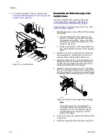
Use this procedure to remove the entire isolation
valve (227) from the isolation cabinet for service.
1.
Prepare the isolation system for service. Follow
the steps under
Prepare the Isolation System for
2.
Use a flat blade screwdriver to open the isolation
cabinet door.
3.
Slide the electrostatic shield (82) up to remove.
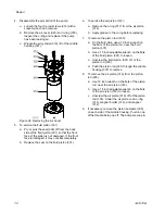
4.
Remove the isolation valve cover (99):
a.
Unscrew and remove the top screw (100)
and washers (19, 22).
b.
Unscrew and remove the bottom screw (100)
and washers (19, 22).
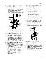
5.
Disconnect the wash fluid reservoir (69).
6.
Before removing the two sensors from the
isolation valve, mark the location of each as a
guide when reassembling.
7.
Remove the sensors from the isolation valve:
a.
Loosen the top clamp and then disconnect
the sensor from the clamp.
b.
Loosen the bottom clamp and then
disconnect the sensor from the clamp.
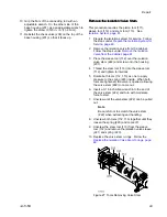
8.
Disconnect the three push-connect air line fittings
(239) to the air cylinder: top, middle, bottom.
9.
Remove the two fluid lines from the air cylinder:
a.
Inlet npsm fitting (72).
b.
Outlet npsm fitting (71). Instead of removing
fluid fitting (72), it is also possible to remove
the hose (76) from either the air cylinder or
from the pump (K).
10. Disconnect the isolation valve from the cabinet
stand (9). On opposing sides of the cabinet
stand, use a 3/16 inch Allen wrench and a 7/16
inch wrench to remove:
a.
The top front and back bolts (23) and
washers (19, 22) on the isolation valve cover
bracket (98).
b.
The bottom front and back bolts (23) and
washers (19, 22) on the isolation valve cover
bracket (98).
11. Lift the isolation valve out of the cabinet.
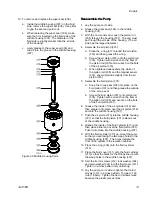
Reinstall
Reinstall
Reinstall the
the
the Isolation
Isolation
Isolation Valve
Valve
Valve into
into
into the
the
the Cabinet
Cabinet
Cabinet
Use this procedure to reinstall the entire isolation
valve (227) into the isolation cabinet after servicing.
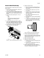
1.
Attach the isolation valve to the top of the cabinet
stand (9):
a.
The front screw (54) also holds the top
bracket for the isolation valve cover (98).
Insert the two screws (54) through the block
mount (224) and then insert into the top two
holes of the cabinet stand (9).
b.
Thread the front bracket (16) onto the front
screw, followed by the washer (19), lock
washer (22), and hex nut (23). Tighten with
a wrench.
c.
Thread the back bracket (98) onto the back
screw, followed by the washer (19), lock
washer (22), and hex nut (23). Tighten with
a wrench.
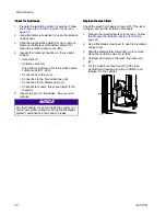
Figure 22 Block Mount Attached to Cabinet
Stand
3A7370B
61


