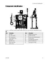
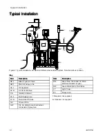


Connect
Connect
Connect the
the
the Waterborne
Waterborne
Waterborne Fluid
Fluid
Fluid Hose
Hose
Hose
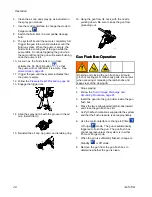
Always use a Graco waterborne fluid hose between
the voltage isolation system fluid outlet and the gun
fluid inlet.
Before connecting the waterborne fluid hose to the
gun, blow it out with air and flush with water to
remove contaminants. Flush the gun before using it.
To reduce the risk of electric shock, install only
one continuous Graco waterborne hose between
the isolated fluid supply and the gun. Do not splice
hoses together.
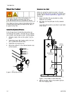
1.
Remove the gun air inlet fitting (21).
Note
This fitting uses a left-hand thread.
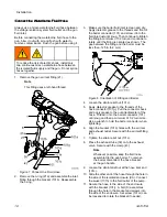
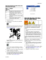
Figure 7 Connect the Fluid Hose
2.
Remove the o-ring (21a) and assemble the inlet
fitting through the bracket (101b). Reassemble
the o-ring.
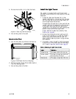
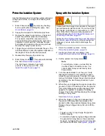
3.
Make sure the barrel fluid inlet is clean and dry.
Apply dielectric grease to the threads and front of
the barrel connector (101) and screw it into the
fluid inlet just until snug. Then continue to tighten
the fitting a minimum of 1/2 turn and continue to
rotate until the fitting is oriented as shown. The
gap between the fitting and the barrel must be
less than .125 in (3.2 mm).
Figure 8 Orientation of Fitting and Barrel
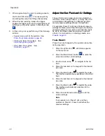
4.
Loosen the strain relief nut (101c).
5.
Apply dielectric grease to the threads of the
hose connector (101g). Pull the connector back
and apply grease to the outside diameter of the
hose. Thread it into the barrel connector (101)
until snug and then a minimum of 1/2 turn more.
Use a wrench to hold the barrel connector when
tightening.
6.
Align the bracket (101b) holes with the air inlet
and exhaust outlet. Secure with the air inlet fitting
(21).
7.
Tighten the strain relief nut (101c).
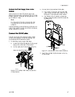
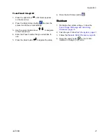
8.
Press the exhaust tube (36) onto the exhaust
valve. Secure with the clamp (43).
Note
Whenever possible, keep the fluid hose
assembled to the gun barrel. To remove
the barrel, disconnect the hose bracket
at the gun handle.
9.
Loosen the strain relief nut at the hose inlet end
(101c).
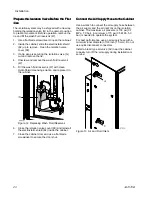
10. Slide the other end of the hose through the hole in
the side of the isolated enclosure (CA). Connect
the swivel (101h) to the fluid outlet of the pump.
11. Secure the hose to the side of the enclosure
with the bracket (101j). A bolt (S) assembles
through the hole in the bracket and screws into
the side of the enclosure. Set screw (101m) can
be loosened to rotate the bracket if needed.
18
3A7370B


