


8
307619
Operation
Pressure Relief Procedure
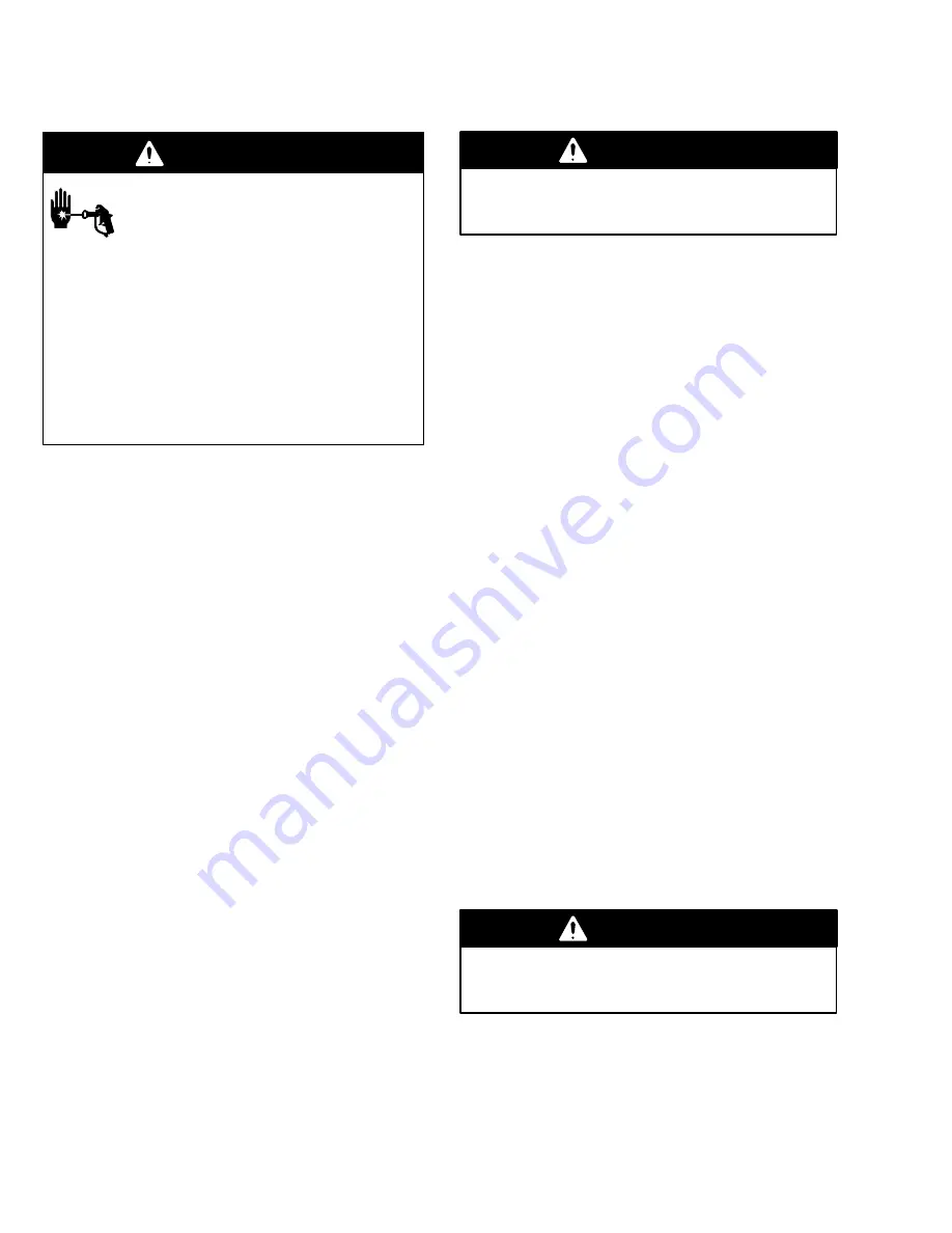
WARNING
SKIN INJECTION HAZARD
The system pressure must be manually
relieved to prevent the system from
starting or spraying accidentally. Fluid
under high pressure can be injected through the
skin and cause serious injury. To reduce the risk of
an injury from injection, splashing fluid, or moving
parts, follow the Pressure Relief Procedure
whenever you:
D
are instructed to relieve the pressure,
D
stop spraying,
D
check or service any of the system equipment,
D
or install or clean the spray tip.
1.
Lock the gun trigger safety.
2.
Shut off the air supply to the pump.
3.
Close the bleed-type master air valve (required in
your system).
4.
Unlock the gun trigger safety.
5.
Hold a metal part of the gun firmly to the side of a
grounded metal pail, and trigger the gun to relieve
pressure.
6.
Lock the gun trigger safety.
7.
Open the drain valve (required in your system),
and have a container ready to catch the drainage.
8.
Leave the drain valve open until you are ready to
spray again.
If you suspect that the spray tip or hose is completely
clogged, or that pressure has not been fully relieved
after following the steps above, very slowly loosen the
tip guard retaining nut or hose end coupling and relieve
pressure gradually, then loosen it completely. Then
clear the tip or hose.
Flush the Pump Before First Use
The pump is tested with lightweight oil, which is left in
to protect the pump parts. If the fluid you are using
may be contaminated by the oil, flush it out with a
compatible solvent before using the pump. If the pump
is being used to supply a circulating system, allow the
solvent to circulate until the pump is thoroughly
flushed. See Flushing the Pump on page 9.
Packing Nut/Wet-Cup
WARNING
To reduce the risk of serious injury whenever you
are instructed to relieve pressure, always follow the
Pressure Relief Procedure at left.
Keep the packing nut/wet-cup (104) filled with Graco
Throat Seal Liquid (TSL) or compatible solvent to help
prolong the packing life. Ensure weekly that the
packing nut is torqued to 18 to 20 ft-lb (24 to 27 N.m);
do not overtighten it. See Fig. 3 on page 11. Relieve
the pressure before adjusting the packing nut or
adding TSL.
Starting and Adjusting the Pump
Begin these steps before you install the spray tip.
1.
Ensure that the air regulator (E) and bleed-type
master air valve (D) are closed. See Fig. 2 on
page 6.
2.
Connect a suction hose (N) to the pump’s fluid
inlet, or lower the pump into a fluid supply
container.
3.
Hold a metal part of the spray gun (M) firmly to the
side of a grounded metal pail and hold the trigger
open.
4.
Open the pump’s bleed-type master air valve (D).
5.
Slowly open the air regulator (E) until the pump
starts (approximately 40 psi [0.28 MPa, 2.8 bar]).
6.
Cycle the pump slowly until all the air is pushed
out and the pump and hoses are fully primed.
7.
Release the spray gun trigger and lock the trigger
safety. The pump should stall against pressure
when you release the trigger.
WARNING
To reduce the risk of serious injury whenever you
are instructed to relieve pressure, always follow the
Pressure Relief Procedure at left.
8.
Relieve the pressure.
9.
Install the spray tip in the gun.
Continued on page 9.
Summary of Contents for HYDRA-SPRAY Monark 223596
Page 22: ...22 307619 Notes...


