background image

Installation 

10

311052E

Connect Fluid Line

1.

Install a fluid filter and drain valve(s) close to the 
pump's fluid outlet.

2.

Install a fluid pressure regulator to control fluid pres-
sure to the gun.

3.

Install a fluid shutoff valve to shut off the fluid supply 
to the gun. 

4.

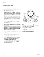
Install an in-line fluid filter on the gun fluid inlet (F) to 
avoid clogging the spray tip with particles from the 
fluid. See F

IG

. 6.

5.

In a circulating system, connect a grounded fluid 
supply hose to the gun fluid fitting. Connect a 
grounded return hose to the other port.

In a non-circulating system, remove the gun fluid 
outlet fitting (G) and plug the outlet port with the 
pipe plug (109) supplied.

Before connecting the fluid line, blow it out with air 
and flush it with solvent. Use solvent that is compat-
ible with the fluid to be sprayed.

A fluid drain valve(s) is required in your system to 
assist in relieving fluid pressure in the displacement 
pump, hose and gun; triggering the gun to relieve 
pressure may not be sufficient.

A fluid pressure regulator must be installed in the 
system if the pump's maximum working pressure 
exceeds the gun's maximum fluid working pressure 
(see the front cover).

Some applications require fine-tuned control of fluid 
pressure. You can control fluid pressure more accu-
rately with a fluid pressure regulator than by regu-
lating the air pressure to the pump.

F

IG

. 6: Side Mounted Manifold Ports

FAN

ATOM

CYL

Cylinder Air Inlet: accepts 1/4 in. (6.3 mm) O.D. tubing
Atomization Air Inlet: 1/4-18.6 npsm
Fan Air Inlet: 1/4-18.6 npsm
Fluid Inlet: 1/4-18 nptf or #5 JIC (1/2-20 unf)
Fluid Outlet (circulating gun only): 1/4-18 nptf or #5 JIC 
(1/2-20 unf)

KEY

C

D

E

F
G

C

F (or G)

G (or F)

E

D

TI8113a

Summary of Contents for G40

Page 1: ... use in explosive atmospheres 4000 psi 28 MPa 280 bar Maximum Working Fluid Pressure 100 psi 0 7 MPa 7 bar Maximum Working Air Pressure See page 3 for model information Important Safety Instructions Read all warnings and instructions in this manual Save these instructions TI8087b Part No 288046 Spray Gun shown mounted on Part No 288217 Manifold II 2 G c T6 ...

Page 2: ...y Pattern Troubleshooting 19 Service 20 Disassembly 20 Diffuser Seat Replacement 23 Reassembly 23 Parts 24 Notes 30 AAP Series Tip and Air Cap Selection Charts 31 LTX Series RAC Tip Selection Charts 32 RAC Switch Tips 33 Accessories 34 Dimensions 36 Mounting Hole Layout 37 Mounting Hole Layout 38 Technical Data 39 Graco Standard Warranty 40 Graco Information 40 Related Manuals The Automatic Air As...

Page 3: ...plas tic seat for acid catalyzed or thin fluids Best results when used with non abrasive fluids at pressures below 1500 psi 10 5 MPa 105 bar Includes AAP series tip of choice G40 RAC Spray Gun 288053 Series A High pressure spray gun with AA Reverse A Clean RAC assembly and Carbide ball and Carbide Seat Includes LTX Series RAC tip of choice A manifold is required for each gun to be installed Refer ...

Page 4: ...ver bend hoses or use hoses to pull equipment Keep children and animals away from work area Comply with all applicable safety regulations SKIN INJECTION HAZARD High pressure fluid from gun hose leaks or ruptured components will pierce skin This may look like just a cut but it is a serious injury that can result in amputation Get immediate surgical treatment Do not point gun at anyone or at any par...

Page 5: ... cause serious injury or death if splashed in the eyes or on skin inhaled or swallowed Read MSDS s to know the specific hazards of the fluids you are using Store hazardous fluid in approved containers and dispose of it according to applicable guidelines PERSONAL PROTECTIVE EQUIPMENT You must wear appropriate protective equipment when operating servicing or when in the operating area of the equipme...

Page 6: ...3 N m Non circulating System 1 See FIG 1 Apply anti seize lubricant 222955 to the threads and mating faces of the manifold 101 plug 109 and elbow 107 supplied unassembled 2 Install an elbow 107 in one fluid port of the mani fold 101 and a plug 109 in the other port 3 Install the internal plug 5 in the gun fluid port on the same side as the manifold plug 4 Connect the fluid supply line to the manif...

Page 7: ...mendations Ground Air Fluid and Hydraulic Hoses Connected To Pump Use only electrically conductive hoses with a maximum of 100 ft 30 5 m combined hose length to ensure grounding continuity Check the electrical resistance of your air and fluid hoses at least once a week If the total resistance to ground exceeds 25 megohms replace the hose immediately Ground Spray Gun Ground the spray gun by mountin...

Page 8: ... Secure the gun to the support with two M5 x 0 8 capscrews S The screws must be long enough to engage the threaded holes in the gun manifold to a depth of 1 4 in 6 mm Retrofit Adapter Plate The retrofit adapter plate enables the manifold to be attached to a variety of bolt patterns To mount the gun using the retrofit adapter plate kit 288197 1 Mount adapter plate to manifold using the three screws...

Page 9: ...f the gun air regulator to shut off air to the gun 6 For manifolds with separate fan and atomization ports connect a separate air supply line to the gun atomizing air inlet D and cylinder air inlet C Con nect an air supply line to the fan air inlet E if desired See FIG 6 For manifolds with a manual fan valve only one supply line is required for both atom ization and fan air A minimum of 50 psi 0 3...

Page 10: ... solvent Use solvent that is compat ible with the fluid to be sprayed A fluid drain valve s is required in your system to assist in relieving fluid pressure in the displacement pump hose and gun triggering the gun to relieve pressure may not be sufficient A fluid pressure regulator must be installed in the system if the pump s maximum working pressure exceeds the gun s maximum fluid working pressu...

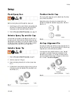
Page 11: ...lot on the air cap See FIG 7 4 Tighten the air cap retaining ring 8 firmly by hand to ensure a good seal between the tip gasket and the diffuser 10 Position the Air Cap The air cap and spray tip position determines the direc tion of the spray pattern Rotate the air cap the spray tip rotates with it as needed to achieve the desired spray pattern direction See FIG 8 Air Cap Alignment Pin Air caps ar...

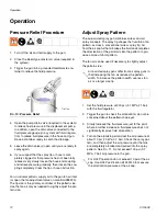
Page 12: ...n of the paint tails into the pattern to pro duce a more uniform pattern The fan air can be used if necessary to slightly adjust the pattern size 1 Set the fluid pressure at 300 psi 2 1 MPa 21 bar with the fluid regulator 2 Trigger the gun to check the atomization do not be concerned about the pattern shape yet 3 Slowly Increase the fluid pressure just to the point where a further increase in flui...

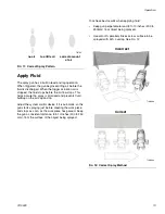
Page 13: ...utomatic so the gun starts spraying just before meeting the work piece and stops as soon as the work piece has passed Keep the gun a consistent distance 8 to 10 inches 200 to 250 mm from the surface of the object being sprayed To achieve best results when applying fluid Keep gun perpendicular and 8 to 10 inches 200 to 250mm from object being sprayed Use smooth parallel strokes across surface to be...

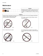
Page 14: ...eft in gun air passages could result in a poor quality paint finish Do not use any cleaning method which may allow solvent into the gun air passages Do not point the gun up while cleaning it Do not immerse the gun in solvent Do not wipe the gun with a cloth soaked in solvent ring out the excess Do not use metal tools to clean the air cap holes as this may scratch them scratches can distort the spr...

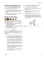
Page 15: ...o reduce the risk of serious injury including splash ing fluid in the eyes or on the skin or static electric discharge when flushing Ensure that the entire system including flushing pails are properly grounded Remove the spray tip Maintain metal to metal contact between the gun and the flushing pail Use the lowest possible pressure CAUTION This gun is not adjustable To ensure proper shutoff screw ...

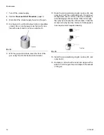
Page 16: ...brush and solvent 12 Scrub the air cap retaining ring 8 air cap 30 and spray tip 9 with the soft bristle brush To clean out air cap holes use a soft tool such as a toothpick to avoid damaging critical surfaces Blow air through the spray tip to ensure the orifice is clean Clean the air cap and spray tip daily minimum Some applica tions require more frequent cleaning 13 Install the air cap retaining...

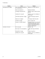
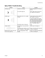
Page 17: ...y 20 Replace piston assembly Air does not shut off Piston assembly not seating properly Broken return spring 29 Swollen o ring 22 Worn piston stem o rings 25 26 Bottom gasket 16 failed Clean service piston assembly Replace worn or swollen o rings Replace spring Replace o rings Replace o rings Replace gasket Fluid leakage from front of gun Fluid needle 14 dirty worn or dam aged Dirty or worn diffus...

Page 18: ... bly 20 Replace o ring Do not immerse pis ton in solvent Increase air pressure or clean air line Clean spray tip and air cap 30 Clean or replace filter Move plug to fluid port consistent with manifold plumbing unless you are using gun in a circulating system If you are all fluid ports in gun and on manifold should be open Fluid does not shut off Worn o ring 25 Piston cap 27 not fully tightened Spr...

Page 19: ...ssary To improve sealing when spraying lightweight materials and sealing life when spraying acid catalyzed materi als use needle SST available with 1 8 in ball only and diffuser seat plastic See Parts page 25 Clean Irregular pattern Fluid build up or spray tip partially plugged On defective side of pattern air horn holes are partially or totally plugged Clean spray tip See page 15 Clean air horn h...

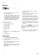
Page 20: ...upplied wrench 38 loosen the fluid needle setscrew 19 Remove the needle stop 21 7 Trigger the gun or remove cap 27 and springs 28 29 to pull the needle housing off the seat while you unscrew the diffuser 10 from the gun body 1 8 Unscrew the needle assembly 14 and use 5 16 in nut driver to pull the assembly straight out the front of the gun 9 Remove the piston Using a pliers pull the piston 20 out ...

Page 21: ...ey are loose replace the entire piston assembly 20 12 Perform the following applicable step a Non circulating guns Remove the fluid outlet port plug 5 and gasket 4 from the fluid hous ing 2 Remove the o ring 6 and backup o ring 7 from the plug b Circulating guns Remove the gasket 4 from the fluid housing 2 13 Clean all parts and replace any worn parts When assembling lubricate the threads with ant...

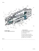
Page 22: ... not lubricate Torque to 155 165 in lb 18 19 N m Apply semi permanent anaerobic sealant Torque to 4 5 in lb 0 45 0 56 N m Tighten cap 27 until it bottoms out 4 3 2 8 7 6 5 Cutaway View Part No 288044 Gun Shown 30 8 9 9a 23 25 2 1 2 2 3 3 3 4 6 7 8 27 22 21 19 28 29 20 16 14 26 1 15 5 2 2 10f 4 TI8123a 10e 10 10a 10d 2 ...

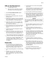
Page 23: ...ve the protective paper from the sticky side of the gasket 16 and adhere the gasket to the bot tom of the piston housing 1 making sure the three holes in the gasket are properly aligned with the matching holes in the housing 7 Insert the needle assembly 14 into the front of the fluid housing 2 Tighten to 50 60 in lb 5 7 6 8 N m 8 Lubricate the threads of the diffuser seat 10 Screw it into the flui...

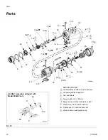
Page 24: ... 65 in lb 7 3 N m Apply semi permanent anaerobic sealant Torque to 4 5 in lb 0 45 0 56 N m Tighten cap 27 until it bottoms out Used on non circulating guns only 4 3 2 8 7 6 5 9 30 9 14 4 6 5 21 19 14 ref 22 17 20 25 26 1 23 4 5 2 2 2 3 3 9 9 9 8 6 7 3 2 3 3 3 TI8088b 44 42 18 10f 10e 10d 10c 10b 10g 43 10a 9a 11 9 46 AA RAC Assembly included with Model 288053 only TI8228a 8 ...

Page 25: ... 10c NUT seat 1 10d 111116 PACKING o ring seat PTFE 1 10e 109450 PACKING o ring PTFE 1 10f 111457 PACKING o ring PTFE 1 10g 15F409 GASKET seat Diffuser assy with carbide seat only 1 11 15J770 HOUSING RAC 1 14 NEEDLE assy 1 288190 SST ball Model 288044 288191 Carbide ball Models 288046 288053 15 15H316 GASKET polyethylene front 1 16 114134 GASKET polyethylene bottom 1 17 15H317 SCREW mounting manif...

Page 26: ...46 SCREW set 5 16 0 437 in long 1 107 2 114342 ELBOW street 1 4 in npt 114247 FITTING elbow male 5 JIC x 1 4 npt 108 2 120389 FITTING tube air line 3 8 in OD tube x 1 4 npt 120537 FITTING tube air line 8 mm OD tube x 1 4 npt 109 101970 PLUG pipe SST 1 4 18 ptf sup plied to plug fluid outlet port in non circulating applications 3 114 120453 SCREW SCHS M3 x 18 1 FIG 19 North America and Internationa...

Page 27: ...6 NIPPLE SST 1 4 npsm straight pipe thread x 1 4 npt 2 108 120389 FITTING tube air line 3 8 in OD tube x 1 4 npt 2 109 101970 PLUG pipe SST 1 4 18 ptf sup plied to plug fluid outlet port in non circulating applications 1 114 120453 SCREW SCHS M3 x 18 1 FIG 20 Manifold with Bottom Fluid Ports Apply anti seize lubricant 222955 to threads and mating faces of manifold 101 and any fittings and or plugs...

Page 28: ...G tube air line 3 8 in OD tube x 1 4 npt 8 mm OD tube x 1 4 npt 4 mm OD tube x 1 4 npt shipped loose 1 107 114246 SCREW set 5 16 0 437 in long 1 108 114342 114247 ELBOW male 1 4 18 npt 5 JIC x 1 4 18 npt 2 109 101970 PLUG pipe SST 1 4 18 ptf supplied to plug fluid outlet port in non circulating applications 1 114 120453 SCREW SCHS M3 x 18 1 FIG 21 Side Fluid Ports and Fan Adjustment Valve TI0556b ...

Page 29: ...FE 2 110 114246 SCREW set hex soc 1 111 2 120389 FITTING tube air line 3 8 in OD tube x 1 4 npt 120537 FITTING tube air line 8 mm OD tube x 1 4 npt 112 1 120388 FITTING tube air inlet 1 4 in OD tube x 1 8 npt m 120538 FITTING tube air inlet 6 mm OD tube x 1 8 npt m 113 103253 SCREW set 2 FIG 22 TI8200a Apply sealant to threads and mating faces of manifold 101 and any fittings and or plugs used in ...

Page 30: ...Notes 30 311052E Notes ...

Page 31: ...Pa 41 bar at 1000 psi 7 0 MPa 70 bar 5 127 7 178 9 228 11 279 13 330 15 381 17 432 0 009 0 229 7 0 0 2 9 1 0 27 209 309 409 509 0 011 0 279 10 0 0 3 13 0 0 4 211 311 411 511 611 0 013 0 330 13 0 0 4 16 9 0 5 213 313 413 513 613 713 0 015 0 381 17 0 0 5 22 0 0 7 215 315 415 515 615 715 815 0 017 0 432 22 0 0 7 28 5 0 85 317 417 517 617 717 817 0 019 0 483 28 0 0 8 36 3 1 09 419 519 619 719 0 021 0 ...

Page 32: ...fl oz min lpm at 2000 psi 14 0 MPa 140 bar Maximum Pattern Width at 12 in 300 mm 4 to 6 150 6 to 8 200 8 to 10 250 10 to 12 300 12 to 14 350 0 009 0 229 11 2 0 33 209 309 0 011 0 279 16 6 0 49 211 311 411 511 0 013 0 330 23 3 0 69 213 313 413 513 0 015 0 381 30 8 0 91 215 315 415 515 615 0 017 0 432 39 5 1 17 217 317 417 517 617 0 019 0 483 49 7 1 47 219 319 419 519 619 0 021 0 533 60 5 1 79 321 4...

Page 33: ...0 10 to 12 300 12 to 14 350 0 008 0 203 8 8 0 26 208 308 0 010 0 254 13 9 0 41 210 310 410 510 0 012 0 305 19 9 0 59 212 312 412 512 612 0 014 0 356 27 0 0 80 214 314 414 514 614 Order desired tip Part No WRXxxx where xxx is the size code for the chart Orifice Size in mm Fluid Output fl oz min lpm Maximum Pattern Width at 12 in 305 mm at 2000 psi 14 0 MPa 140 bar 24 in 610 0 021 0 533 60 5 1 79 12...

Page 34: ...stic seat HVLP Air Cap Verification Kit 249140 Use to determine air pressure behind the air cap Do not use for actual spraying Lacquer Air Cap Kit 289080 Kit includes air cap for optimized spray of lacquer mate rials RAC Gasket 246453 Pack of five standard replacement RAC gaskets Acetal RAC Gasket 248936 Pack of five plastic acetal replacement RAC gaskets Gasket Filter 288201 Optional 100 mesh fil...

Page 35: ...e gun s fluid connector 1 4 18 npsm Includes the parts shown below High Pressure Ball Valves Fluoroelastomer Seals 5000 psi 34 MPa 345 bar Maximum Working Pressure Can be used as fluid drain valve 210657 1 2 npt m 210658 3 8 npt m 210659 3 8 x 1 4 npt m Bleed type Master Air Valve 300 psi 2 1 MPa 21 bar Maximum Working Pressure Relieves air trapped in the air line between the pump air inlet and th...

Page 36: ...Dimensions 36 311052E Dimensions FIG 24 2 0 in 50 8 mm 3 86 in 98 0 m 3 0 in 76 2 mm 4 9 in 124 5 mm TI8113a TI8127a 1 375 in 34 9 mm 2 0 in 50 8 mm 2 40 in 60 96 mm ...

Page 37: ... 4 in 10 2 mm 6 3 mm holes 0 805 in 20 5 mm 0 187 in 4 8 mm 1 375 in 35 mm 2 125 in 54 mm TI8127a 1 750 in 44 5 mm Two M5 x 0 8 x 0 25 in Two 0 128 diameter x 0 31 in 7 8 mm deep holes for alignment pin Remove set screws when using bottom mounting pattern 0 5 in 12 7 mm ...

Page 38: ...Retrofit Adapter Plate TI8178a 2 007 in 50 98 mm 1 375 in 34 93 mm 0 736 in 18 69 mm 2 250 in 57 15 mm Gun with Rear Port Manifold 1 765 in 44 83 mm 2 325 in 59 06 mm 2 400 in 60 96 mm 3 720 in 94 49 mm 3 200 in 81 28 mm TI8231a TI8226a 1 375 in 34 93 mm 0 400 in 10 16 mm 0 875 in 22 23 mm 1 010 in 25 65 mm 0 205 in 5 21 mm 0 375 in 9 53 mm ...

Page 39: ...ar Weight 1 2 lbs 965 g Wetted Parts Stainless Steel Carbide Ultra High Molecular Weight Polyethylene Chemically Resistant Fluoroelastomer Engineered Plastic PTFE Polyamide Models 3 16 in ball Cylinder Air Pressure psi MPa bar Fluid Pressure psi MPa bar msec to fully open msec to fully close 50 0 34 3 4 600 4 2 42 60 60 50 0 34 3 4 1800 12 4 124 60 60 50 0 34 3 4 4000 28 280 60 60 Air Cap Part No ...

Page 40: ...al or workmanship repairs will be made at a reasonable charge which charges may include the costs of parts labor and transportation THIS WARRANTY IS EXCLUSIVE AND IS IN LIEU OF ANY OTHER WARRANTIES EXPRESS OR IMPLIED INCLUDING BUT NOT LIMITED TO WARRANTY OF MERCHANTABILITY OR WARRANTY OF FITNESS FOR A PARTICULAR PURPOSE Graco s sole obligation and buyer s sole remedy for any breach of warranty sha...

Reviews: