AAP Series Tip and Air Cap Selection Charts
311052E
31
AAP Series Tip and Air Cap Selection Charts
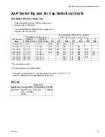
AAP Series Precision Spray Tips
.
* Tips are tested in water.
† Tip sizes include a 150 mesh tip filter
Air Cap
Order desired tip (Part No. AAPxxx) where xxx is
the size code for the chart.
Tips are physically marked with Xxxx, where xxx is
the size code from the chart.
Orifice Size in.
(mm)
* Fluid Output, fl oz/min (lpm)
Maximum Pattern Width at 12 in. (300mm)
Pattern Width Tol/- 0.5 in. (13.0 mm)
at 600 psi
(4.1 MPa, 41 bar)
at 1000 psi
(7.0 MPa, 70 bar)
5
(127)
7
(178)
9
(228)
11
(279)
13
(330)
15
(381)
17
(432)
† 0.009 (0.229)
7.0 (0.2)
9.1 (0.27)
209
309
409
509
† 0.011 (0.279)
10.0 (0.3)
13.0 (0.4)
211
311
411
511
611
0.013 (0.330)
13.0 (0.4)
16.9 (0.5)
213
313
413
513
613
713
0.015 (0.381)
17.0 (0.5)
22.0 (0.7)
215
315
415
515
615
715
815
0.017 (0.432)
22.0 (0.7)
28.5 (0.85)
317
417
517
617
717
817
0.019 (0.483)
28.0 (0.8)
36.3 (1.09)
419
519
619
719
0.021 (0.533)
35.0 (1.0)
45.4 (1.36)
421
521
621
Fluid output (Q) at other pressures (P) can be calculated by this formula: Q = (0.041) (QT)
where QT = fluid output (fl oz/min) from the above table for 600 psi.
P
Application Tip Used With
Typical Air
Consumption Part No.
Standard
All AAP, GG4,
GG5, and AAM
Series
3-6 scfm
288194
Summary of Contents for G40
Page 30: ...Notes 30 311052E Notes ...


