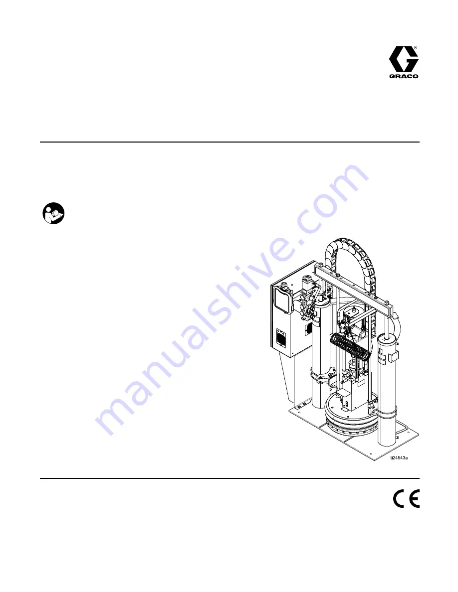
background image

Instructions-Parts

Therm-O-Flow® 200

334130A

EN

For applying hot melt sealant and adhesive materials from 200 Liter (55 Gallon) drums. For professional

use only.

Not approved for use in European explosive atmosphere locations.

Important Safety Instructions

Read all warnings and instructions in this manual and in related

manuals. Save these instructions.

Maximum Operating Temperature 400°F

(204 °C)

See page 6 for model information.

See Technical Specifications, page 107,

for maximum working pressures.

PROVEN QUALITY. LEADING TECHNOLOGY.

Summary of Contents for 334130A

Page 1: ...approved for use in European explosive atmosphere locations Important Safety Instructions Read all warnings and instructions in this manual and in related manuals Save these instructions MaximumOpera...

Page 2: ...s 46 Replace Platen RTD 46 Separate the Air Motor and Pump 47 Remove Platen 49 Replace Heater Bands and Pump RTD 50 Replace MZLP Fuse 51 Replace MZLP 52 Replace MZLP Daughter Card 53 Replace AWB 54 Re...

Page 3: ...ZARD Moving parts can pinch cut or amputate ngers and other body parts Keep clear of moving parts Do not operate equipment with protective guards or covers removed Pressurized equipment can start with...

Page 4: ...before cleaning checking or servicing equipment Tighten all uid connections before operating the equipment Check hoses and couplings daily Replace worn or damaged parts immediately FIRE AND EXPLOSION...

Page 5: ...mmediately with genuine manufacturer s replacement parts only Do not alter or modify equipment Alterations or modi cations may void agency approvals and create safety hazards Make sure all equipment i...

Page 6: ...4S 8 Zones 480 V Secondary 25P 8 Zones 575 V Primary 25S 8 Zones 575 V Secondary 31P 12 Zones 230 V Primary 31S 12 Zones 230 V Secondary 32P 12 Zones 400 V N Primary 32S 12 Zones 400 V N Secondary 33P...

Page 7: ...r Parts 334128 Check Mate 800 Throat Seal Repair Kit Repair Parts Ram Manual 334198 Therm O Flow 200 Pneumatic and Hydraulic Ram Instructions Parts Accessory and Kit Manuals 309160 Heated Hose Instruc...

Page 8: ...odule MZLP C Light Tower D Cable Track E Ram F Heated Pump G Heated Platen H Integrated Air Controls 3 4 in npt inlet J Electrical Control Panel Key K Main Power Switch L ADM M Air Motor Solenoid N El...

Page 9: ...Blowoff Button Turns air on and off to push the platen out of an empty drum Key CH Blowoff Pressure Gauge Displays the blowoff pressure CJ Blowoff Air Regulator Controls platen blowoff pressure CK Ai...

Page 10: ...Component Identification Electrical Control Enclosure Figure 3 Electrical Enclosure 10 334130A...

Page 11: ...ule MZLP DB Ventilation Grill DC Electrical Control Panel DD Automatic Wiring Board AWB DE Power Supply 24V DF Residual Current Device GFI 63A Key DG Platen SSR 65A DH Platen Contactor DJ Platen Fuse...

Page 12: ...endix B USB Data page 103 NOTICE To prevent damage to the softkey buttons do not press buttons with sharp objects such as pens plastic cards or ngernails Figure 4 Front View Key Function BA Heating sy...

Page 13: ...Solid Run Mode System On Green Flashing Setup Mode System On System Status Yellow Solid Run Mode System Off Green Flashing Data recording in progress Yellow Solid Downloading information to USB USB S...

Page 14: ...nt temperature Flashing green system status indicator LED on the ADM Heat is increasing to setpoint temperature Pump is off Heat Soak Heat zones are all at temperature Material is soaking for a user s...

Page 15: ...all air and uid hoses are properly sized for the system Heat Control Zone The Therm O Flow has 4 8 or 12 heat zones Zones for the heated drum platen and the heated pump are not included in the zone co...

Page 16: ...r the pump and ram are fully accessible with room to stand directly in front of the pneumatic control panel and the electrical control panel 4 Make sure there is easy access to an appropriate electric...

Page 17: ...mm air line from an air source to the system air inlet H capable of delivering a minimum of 25 50 cfm at 100 psi 0 7 MPa 7 0 bar Do not use quick disconnects Figure 8 Air Connection 4 Ensure drum low...

Page 18: ...cessories and Kits page 89 for available ttings and heated hoses Figure 9 2 Wrap exposed ttings on the pump outlet with Nomex insulation and secure insulation using berglass tape 3 Connect large heate...

Page 19: ...Figure 11 Heated Manifold 243697 Note The heated manifold part no 243697 is included with all secondary systems See Accessories and Kits page 89 for available manifolds 7 Use 2 wrenches to tighten ho...

Page 20: ...g box to connect heated hoses to the electrical enclosure For additional cables heated hose and uid control devices see Accessories and Kits page 89 Connect uid control devices to a heated hose or the...

Page 21: ...h Bottom 1 Locate the opening in the control panel s top housing for the conduit that will enclose the wire from the facility s power source The hole will accept a a cord diameter range of 0 7 1 2 in...

Page 22: ...ollow local code Use only metal drums placed on a grounded surface Do not place the drum on a nonconductive surface such as paper or cardboard which interrupts the grounding continuity To maintain gro...

Page 23: ...e A J Second Heat Zone C D First RTD G K Second RTD M K Earth Ground B G F E D C B A K L M J H ti24580a 3 Replace any parts whose resistance readings do not comply with the ranges listed in the RTD Se...

Page 24: ...eck resistance at ambient room temperature 63 77 F 17 25 C Table 4 Heaters Component Between Terminals For Unit Voltage Platen Model Code Resistance Values ohms EM 8 25 1 2 AD BE FC 220 240 VAC EF ES...

Page 25: ...setback temperatures for the pump platen and heat zones on the Heat A screens Note Setback temperatures must be at least 20 F 10 C lower than the setpoint temperatures Note To ensure accurate hose tem...

Page 26: ...of grams or pounds 9 To setup the optional Schedule function see Schedule page 37 The schedule function allows the system to automatically enable and disable heating and setback at speci ed times 10...

Page 27: ...it Low See Run State Chart Run State Bit Low See Run State Chart 2 Run State Bit High See Run State Chart Run State Bit High See Run State Chart 3 Error State Bit Low See Error State Chart Unit B IS A...

Page 28: ...or each signal See the following table for pin assignments Figure 15 H1 Customer Input H2 Customer Output Signal Pin Signal Pin 1 1 2 1 1 2 2 3 4 2 3 4 3 5 6 3 5 6 4 7 8 4 7 8 Inputs High 10 30 VDC Lo...

Page 29: ...iagrams show how to connect customer inputs and outputs to the MZLP For convenience each system ships with connector kit 24P176 If a connector is lost or damaged order kit 24P176 for replacements Figu...

Page 30: ...s See Technical Speci cations in all of the equipment manuals 1 Select the material for the initial material load 2 Verify whether the factory test oil and the initial material load are compatible a I...

Page 31: ...en G begins to rise Figure 18 Raise the Platen 3 Apply a thin coating of high temperature grease lubricant part no 115982 to the platen drum seals 4 Fill displacement pump wet cup 2 3 full with Graco...

Page 32: ...p the dispense valve open over a waste container while the system is heating up and also when cooling down This will prevent a pressure build up caused by uids or gases expanding from the heat Note Op...

Page 33: ...on The indicator light on the solenoid connector will only be on if Enable Pump Autostart is selected on the System 1 Setup screen 4 Adjust the air motor slider valve CM to the open position 5 Adjust...

Page 34: ...ever adjust the regulator by more than 5 psi 34 kPa 0 3 bar increments Make sure the pump begins to cycle and heated material ows from the bleed stem Z after several cycles of the pump 9 Prime the pum...

Page 35: ...m was placed on the frame the pump will cycle until all air has been removed 7 Close the main air slider valve CA and release trigger lock 8 Engage trigger lock Figure 23 Trigger Lock Engaged 9 Press...

Page 36: ...igger lock Figure 24 Engaged 2 Close the system master air slider valve CA 3 Set the ram director valve CC to the neutral position 4 Disengage the trigger lock Figure 25 Disengaged 5 Hold a metal part...

Page 37: ...set using a 24 hour clock Several on and off times can be set each day 1 On the Schedule screen in the Setup screens set the ON times for each day of the week 2 Set the OFF times for each day of the...

Page 38: ...ystems include Low Empty Sensors The air will shutoff to prevent the pump from cavitation If the light tower kit is installed a solid red light indicates that the pail is empty and ready to change In...

Page 39: ...ng the system to stop The alarm needs to be addressed immediately Deviations are indicated by This condition indicates a parameter critical to the process has reached a level requiring attention but n...

Page 40: ...shorts in harness to SSR Check polarity of wiring to SSR Replace if necessary AM4 _ High Current Contactor MZLP _ Alarm Defective or shorted to ground on MZLP Check for shorts in the harness to contac...

Page 41: ...n position and suf cient air is forcing the ram down Pump is trying to feed adhesive no adhesive to feed Melter at incorrect temperature too low Check setpoint and set to manufactures recommendation D...

Page 42: ...s not hotter than this zone s setpoint Check RTD wiring and harness connector integrity T6 _ Sensor Err Unit _ Zone _ Alarm Bad RTD Reading Replace RTD T6C_ AWB Invalid Thermistor Reading Alarm Transf...

Page 43: ...is plugged in at J2 and the AWB is plugged in at J5 and J6 Check incoming voltage is correct for con guration V4M_ AWB High Line Voltage Alarm Incoming voltage is too high Verify the transformer has...

Page 44: ...pers Closed main air valve or clogged air line Open air valve clear air line Not enough air pressure Increase air pressure Worn or damaged ram piston Replace piston See instruction manual 310523 Ram d...

Page 45: ...motor is off Check gauges and valves to the air motor Leak around pump wet cup Worn throat seals Replace throat seals See Servicing the Throat packings in manual 334127 or 334128 Air Motor Troublesho...

Page 46: ...connections 1 If the material drum has already been removed from the supply unit go to step 2 If you need to remove the material drum see Change Drums page 38 2 Make sure the ram plate is down and the...

Page 47: ...t be done with the unit still warm The material and equipment will be hot 1 If the material drum has already been removed from the supply unit go to step 2 If you need to remove the material drum perf...

Page 48: ...rom platen lift rods 15 Remove nuts F from pump air motor stand off rods at the pump end 16 Remove nuts Z and bolts holding cable tract to air motor support plate 17 Slide end of cable track outboard...

Page 49: ...switch off 2 Disconnect the platen power wires and the ground wire from within the main control panel and pull out of conduit 3 Remove the platen assembly from the ram 4 Reverse this procedure to rei...

Page 50: ...ial in a waste container 5 On ADM turn off the system heat D 6 Turn the main power switch off 7 Remove the screws and covers 8 Remove white ceramic caps and disconnect the electrical wires from heater...

Page 51: ...J6 J5 J7 F10 F9 F8 F7 F6 F5 F4 F3 F2 F1 Figure 31 Fuse Locations Fuse Kit Fuse Part F1 F2 250VAC 25A long white ceramic 24V289 F3 F10 250VAC 8A fast acting clear glass Spare fuse kit included with sy...

Page 52: ...onnector and reinstall it on the new MZLP J5 connector 6 To reassemble MZLP Set MZLP rotary switch based on location See MZLP Rotary Switch Table 7 Use four screws 115 to install MZLP 111 or 112 to el...

Page 53: ...ard 112a from the MZLP 1 112 Figure 33 MZLP Daughter Card 5 Plug new daughter card 112a into the MZLP 112 6 Use screws 112b to secure daughter card to MZLP 112 7 Connect cables to new daughter card 11...

Page 54: ...o set the connector If resistance is felt stop and verify the connector orientation Note See Electrical Schematics page 59 if unable to determine the connector location Replace Power Supply 1 Turn the...

Page 55: ...138 and fan 136 7 Mount new fan 136 rear fan grill 138 and nuts 139 on grill 137 with the arrow pointing toward the grill 137 8 Tie down fan wires onto tie down locations on grill 137 using cable zip...

Page 56: ...rom transformer 235 onto J7 connector on AWB 205 11 Reconnect red wire from fan into pin 4 and the black wire into pin 3 of J7 connector 12 Install transformer 235 ground wire onto ground lug of back...

Page 57: ...Repair Figure 35 Inside of Electrical Control Enclosure 334130A 57...

Page 58: ...rogress To prevent corrupting the software load do not remove token until the status screen disappears Note When the screen turns on you will see the following screens First Software is checking which...

Page 59: ...8 1150 1140 1100 1090 1L1 1L2 1L3 1060 1070 1080 1061 1071 1081 1290 1300 1310 SSR 1 FAN 240V 2 4 6 1 3 5 24V A1 A2 1 2 3 4 5 6 24V G N 5 3 N 6 4 1290 1300 1 2 106 107 108 4 5 6 106 109 111 CB 1 1 3...

Page 60: ...A2 1 2 3 4 5 6 24V G 1290 1300 RCD 1 N 5 3 N 6 4 1 2 A B C D E F GND 1290 1300 1310 220 1320 1320 RCD W1 RCD W2 RCD W3 RCD W4 N CB 1 1 3 5 2 4 6 N 1L1 1L2 RCD W1 RCD W2 RCD W3 7 8 1L3 RCD W4 HARNESS...

Page 61: ...1L2 1L3 1060 1070 1080 1061 1071 1081 1290 1300 1310 SSR 1 FAN 240V 2 4 6 1 3 5 24V A1 A2 1 2 3 4 5 6 24V G 1290 1300 RCD 1 N 5 3 N 6 4 1 2 A B C D E F GND 1290 1300 1310 220 1320 1320 RCD W1 RCD W2...

Page 62: ...2 1 G 3 2 1 G 3 2 1 1290 1300 1310 1220 1250 2610 2620 J16 J14 J15 J7 J6 J5 J1 J2 MZTCM 1 J13 J12 L1 L3 G L3 L2 L1 5 4 3 2 1 4 3 2 1 4 3 2 1 5 4 3 2 1 5 4 3 2 1 6 5 4 3 2 1 4 3 2 1 4 3 2 1 4 3 2 1 114...

Page 63: ...18 254 253 252 251 250 215 217 218 MZTCM 3 MZTCM 2 J7 4 3 2 1 J7 J6 J5 J1 J2 L3 L1 G L3 L2 L1 5 4 3 2 1 5 4 3 2 1 6 5 4 3 2 1 4 3 2 1 J3 HARNESS 127511 MZTCM 2 J3 TO MZTCM 3 J6 J6 J5 5 4 3 2 1 6 5 4 3...

Page 64: ...Zones MZTCM 1 J8 J9 C D E F G H J M L K A B ZONE 1 RTD ZONE 2 RTD ZONE 1 START ZONE 2 START ZONE 2 HEAT ZONE 1 HEAT A J C D G F K L M E H B TYPICAL ZONE PIN OUT MZTCM 2 MZTCM 3 J8 J9 J8 J9 2 1 6 5 10...

Page 65: ...Parts Parts Therm O Flow 200 Supply Unit 334130A 65...

Page 66: ...R level low empty 1 14 15H543 BRACKET mounting 1 15 120186 BOLT mounting u bolt 2 Ref Part Description Qty 16 101864 SCREW cap sch 8 17 111303 NUT hex 4 18 100575 SCREW cap hex hd 4 19 100023 WASHER a...

Page 67: ...cal Enclosure Ref Part Description Qty 51 24W870 KIT CONTROL air 3 regulator see manual 334201 1 52 121235 SOLENOID air motor ram 1 53 17A557 HARNESS solenoid MZLP 1 Ref Part Description Qty 54 113445...

Page 68: ...Parts Electrical Module 68 334130A...

Page 69: ...Parts 334130A 69...

Page 70: ...118 WIRE grounding door 1 119 100166 NUT full hex 2 120 GASKET hphm 1 122 17A543 HARNESS power mzlp1 awb 1 Ref Part Description Qty 123 17A544 HARNESS power mzlp2 awb 8 zone assemblies only 1 17A545...

Page 71: ...ry modules only 1 162 16W035 CONNECTOR jumper 8 zone assemblies only Qty 1 12 zone assemblies only Qty 2 163 CONTACT socket 20 24 awg crimp tin 3 164 TUBE 1 16 shrink tube 0 13 Ref Part Description Qt...

Page 72: ...al Panel 230V 400V N Transformer Transformer Panel Shown 1 Torque terminals to 25 27 in lbs 2 8 3 1 N m 2 Torque terminals to 13 3 16 in lbs 1 5 1 8 N m 3 Torque terminals to 4 53 6 2 in lbs 0 5 0 7 N...

Page 73: ...Parts 230V Panel 400V N Panel 1 Torque terminals to 25 27 in lbs 2 8 3 1 N m 2 Torque terminals to 13 3 16 in lbs 1 5 1 8 N m 3 Torque terminals to 4 53 6 2 in lbs 0 5 0 7 N m 334130A 73...

Page 74: ...ER anchor wire tie nylon 12 225 HARNESS wire ground 8awg 1 Ref Part Description Qty 226 HARNESS fuse contactor 1 227 HARNESS contactor ssr 1 228 HARNESS rcd ssr fan 1 81 0196 40 11 FUSE class j 40amp...

Page 75: ...st be fully contained within the sensor mount 322 5 After fastening band clamp 321 secure excess with berglass tape 6 Coat inside of heater 309a 309b only to within 0 75 in 19 mm of vertical ends with...

Page 76: ...BLOCK standoff mounting 3 315 102656 MUFFLER 1 316 186925 NUT coupling 1 317 184129 COLLAR coupling 2 318 120186 BOLT mounting u bolt 2 Ref Part Description Qty 320 120275 SENSOR RTD 1 321 C31012 CLA...

Page 77: ...must be fully contained within the sensor mount 322 5 After fastening band clamp 321 secure excess with berglass tape 6 Coat inside of heater 309 only to within 0 75 in 19 mm of vertical ends with non...

Page 78: ...37 BLOCK standoff mounting 3 315 102656 MUFFLER 1 316 186925 NUT coupling 1 317 184129 COLLAR coupling 2 Ref Part Description Qty 318 120186 BOLT mounting u bolt 2 320 120275 SENSOR RTD 1 321 C31012 C...

Page 79: ...Do not coat sensor 4 Prior to tightening band clamp 412 RTD sensor 410 must be fully contained within the sensor mount 411 5 After fastening band clamp 412 secure excess with berglass tape 6 Coat insi...

Page 80: ...PORT sensor 1 412 C31012 CLAMP 1 413 186925 NUT coupling 1 414 184129 COLLAR coupling 2 415 C38163 WASHER lock ext tooth 1 Ref Part Description Qty 416 CONDUCTOR ground 1 417 C38162 SCREW machine 1 41...

Page 81: ...ont 1 505 24W978 COVER pump top back 506 120792 FASTENER thread cutting screw 12 Ref Part Description Qty 507 184090 LABEL warning 2 508 104088 RIVET blind 4 509 15J075 LABEL safety hot surface and sh...

Page 82: ...Parts Heated Platens 24V633 Heated Drum Platen Mega Flo Code E option M 24V634 Heated Drum Platen Standard Grid Code E option F 24V635 Heated Drum Platen Smooth Bottom no n Code E option S 82 334130A...

Page 83: ...50707 PLATE designation 1 615 100508 SCREW drive 2 616 CONDUCTOR 14 2 ft 4 3 m 6 617 CONDUCTOR 1 7 ft 0 5 m 2 Ref Part Description Qty 618 CONDUCTOR 0 3 ft 0 09 m 4 619 CONDUCTOR ground 1 620 112901 N...

Page 84: ...Parts Heater Terminal Patterns 24V633 24V634 24V635 16 5 Ohms across pairs 19 25 Ohms across pairs Platen Coil Wiring 24V633 24V634 24V635 84 334130A...

Page 85: ...t Description Qty 701 C32424 BOLT U 7 in 177 8 mm 2 702 160111 CLAMP barrel 1 703 100103 PIN cotter 2 704 100307 NUT hex 4 Ref Part Description Qty 705 100133 WASHER lock 4 706 C38182 WASHER plain 2 7...

Page 86: ...hd 8 703 918421 CLAMP back half assembly 1 704 918423 KIT repair 1 705 617395 PIN quick release 2 756 100133 WASHER lock 8 Ref Part Description Qty 707 C19200 WASHER plain 8 708 617433 SPACER drum cla...

Page 87: ...TION H 2 Ref Part Description Qty 6 C32424 BOLT U 7 in 177 8 mm 4 801 C32271 CLAMSHELL 1 802 C19126 SCREW cap hex hd 8 803 100133 WASHER lock 12 Ref Part Description Qty 804 100307 NUT hex 8 805 61734...

Page 88: ...ef Part Description Qty 851 VENT hood 1 852 112166 SCREW cap sch 4 Ref Part Description Qty 853 100016 WASHER lock 4 855 C14038 LABEL warning 1 Replacement Warning labels signs tags and cards are avai...

Page 89: ...Operated Mastic Pressure Regulator 240V 243656 23 1 Heated Pressure Compensator Valve 240V 243657 51 1 Heated Pressure Compensator Valve 240V 243697 Heated Distribution Manifold 240V Includes 2 3 4 n...

Page 90: ...ump Fittings TOF 20 200 PUMP 1 11 1 2 DUAL OUTLET ADD 120263 16V432 100380 253267 253268 120260 120261 120262 TOF MINI 5 PUMP 1 2 NPT DUAL OUTLET ADD 120241 16V432 C20678 C20679 C38006 6301 85 6308 85...

Page 91: ...120267 116766 120267 120268 Mastic Regulator 243700 Inlet Outlet 3 4 in NPTF 16V432 100896 124286 15Y934 C20708 125661 125661 120268 Top and bottom feed guns with and without switch 249512 249513 2495...

Page 92: ...iption Qty 1 MODULE GCA MZLP 1 2 125856 SCREW 8 32 serrated ange 4 3 16T440 CAP souriau UTS14 2 4 127511 CABLE board samtec 1 5 16W035 CONNECTOR jumper 1 Ref Part Description Qty 6 17A544 HARNESS powe...

Page 93: ...will be referred to as MZLP 2 and the original MZLP that came with the system will be referred to as MZLP 1 5 Open the electrical enclosure door Note Do not force the electrical connection Minimal for...

Page 94: ...iption Qty 1 MODULE GCA MZLP 1 2 125856 SCREW 8 32 serrated ange 4 3 16T440 CAP souriau UTS14 2 4 127511 CABLE board samtec 1 5 16W035 CONNECTOR jumper 1 Ref Part Description Qty 6 17A545 HARNESS powe...

Page 95: ...e referred to as MZLP 3 and the other two that came with the system will be referred to as MZLP 1 and MZLP 2 5 Open the electrical enclosure door Note Do not force the electrical connection Minimal fo...

Page 96: ...d on Screen Navigation To switch between the Setup and Operation screens press Use the keypad to navigate between screens Enable Disable Heating System To enable or disable the entire heating system p...

Page 97: ...Meter Pressure Regulator Other Advisory See Error Codes for more information Deviation See Error Codes for more information Alarm See Error Codes for more information Softkey Icons The following icons...

Page 98: ...rm range Color A and B Zone Status Yellow Outside of advisory range Green Yellow Flashing Warmup Events The Events screens store a maximum of 200 events The events list can be downloaded in the USB lo...

Page 99: ...pty 1 Drum Low 2 Pump Cycle Switch Up 3 Pump Cycle Switch Down DO System Digital Outputs 0 Pump Solenoid 1 Not Used 2 Not Used 3 Not Used ISO DI Customer Digital Inputs See Connect PLC page 27 ISO DO...

Page 100: ...ly turns the pump on after reaching setpoint temperature and heat soak is complete Enable Tandem System Enable all secondary system ADM screens Heat Soak Time for to preheat after all zones have reach...

Page 101: ...tal mass dispensed since the last total weight reset is shown on the Home screen and the mass ow rate is shown on the Diagnostic screen Note If the Speci c Gravity is set to zero the Home screen will...

Page 102: ...a heated hose Maintenance A The system will notify the user at the set interval that maintenance is required The elds in boxes can be edited by the user Due and Current are both the number of cycles s...

Page 103: ...RACO 12345678 DOWNLOAD The 8 digit numeric folder name matches the 8 digit ADM serial number which is located on the back of the ADM When downloading from multiple ADMs there will be one sub folder in...

Page 104: ...hours of system operation data or 43 days of around the clock operation Once full the system will overwrite the oldest data GCA Log This log 3 GCA CSV lists the installed GCA modules and their respect...

Page 105: ...ext le that contains two columns The rst column consists of a list of strings in the language selected at the time of download The second column can be used to enter the custom language strings If a c...

Page 106: ...ing and Clearance A in mm B in mm C in mm D in mm E in mm F in mm G in mm J in mm 59 1498 6 40 1016 37 939 21 533 25 635 58 1473 48 1219 11 279 Height H Dimensions Fully Raised 110 in 2794 mm Fully Lo...

Page 107: ...17 4 PH alloy steel ductile iron PTFE Maximum Fluid Working Pressure Merkur 6 0 in 2300 psi 15 9 MPa 159 bar Merkur 7 5 in 3000 psi 20 7 MPa 207 bar NXT 6500 3000 psi 20 7 MPa 207 bar Maximum Air Inp...

Page 108: ...s for lost pro ts lost sales injury to person or property or any other incidental or consequential loss shall be available Any action for breach of warranty must be brought within two 2 years of the d...

Reviews: