background image

Troubleshooting

3A0245A

17

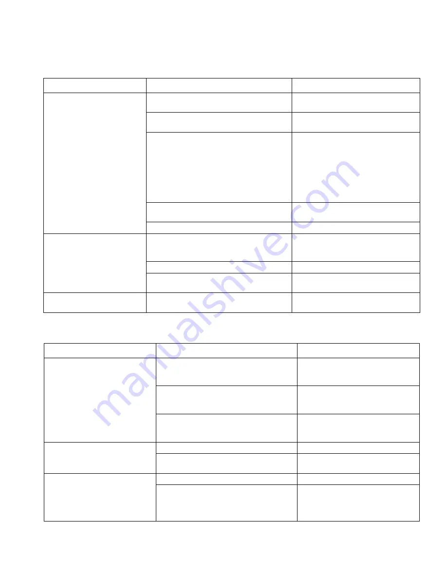
Low or Fluctuating Output (continued)

Electrical Short

PROBLEM

CAUSE

SOLUTION

Motor runs and pump strokes

No material supply.

Refill hopper and re-prime pump.
Clean hopper strainer.

Loose fittings.

Tighten; use thread sealant or sealing 
tape on threads if necessary.

Intake valve ball and piston ball are not seat-
ing properly.

Remove intake and piston valves and 
clean. Check balls and seats for nicks or 
obstructions; replace if necessary, page 
18. Also check piston valve seat for 
hardened material or nicks and replace 
if necessary. Clean hopper before using 
to remove particles that could clog 
pump.

Leaking around throat packing nut which may 
indicate worn or damaged packings.

Replace packing, page 18. 

Pump rod damage.

Repair pump.

Motor runs but pump does not 
stroke

Displacement pump pin (damaged or miss-
ing).

Replace pump pin if missing. Be sure 
retainer spring (76) is fully in groove all 
around connecting rod.

Connecting rod assembly is damaged.

Replace connecting rod assembly.

Gears or drive housing.

Inspect drive housing assembly and 
gears for damage. Replace if needed.

Motor intermittently stops while 
applying material

See RF Problems, page 18.

PROBLEM

CAUSE

SOLUTION

Building circuit breaker opens as 
soon as power switch is turned on.

CAUTION 

Any short in any part of the motor 
power circuit will cause the control 
circuit to inhibit drywall feed pump 
operation. Correctly diagnose and 
repair all shorts before checking 
and replacing control board. 

Electrical wiring insulation damaged, termi-
nals fit loose or are damaged. Also wires 
between motor control and motor. 

Repair or replace damaged wiring or 
terminals. Securely reconnect all 
wires.

Motor armature is shorted. 

Replace motor. Inspect windings for 
burns. Perform motor control board 
diagnosis.

Motor control board.

Replace with a new control board if 
necessary. Perform motor control 
board diagnosis.

Building circuit breaker opens as 
soon as unit is plugged into outlet 
and unit is NOT turned on.

Basic Electrical Problems, see page 15.

Perform necessary procedures.

For damaged or pinched wires in pressure 
control.

Replace damaged parts.

Drywall feed pump quits after unit 
operates for 5 to 10 minutes.

Basic Electrical Problems.

Perform necessary procedures.

Check electrical supply with volt meter. 
Meter must read:
210-255 Vac for 220-240 Vac models;
85-130 Vac for 100-120 Vac models.

If voltage is too high, do not operate 
drywall feed pump until corrected.

Summary of Contents for 257100

Page 1: ...set materials Maximum Working Pressure 2500 psi 17 2 MPa 172 bar Model 257100 120V NA ETL Model 258906 240V Euro Multicord Model 258907 110V UK CE Model 262288 120V NA Model 262300 240V Euro CE Cord...

Page 2: ...able fumes such as solvent and paint fumes in work area can ignite or explode To help prevent fire and explosion Do not dispense flammable or combustible materials near an open flame or sources of ign...

Page 3: ...rugs or alcohol Do not kink or over bend the hose Do not expose the hose to temperatures or to pressures in excess of those specified by Graco Do not use the hose as a strength member to pull or lift...

Page 4: ...me Tool Fill Recirculation Valve Pressure Relief C Flow Control Knob D ON OFF Switch E 15 20 Amp Switch North America only F Material Hoses G Movable Handle H Pump Connector J Prime Hose K Hopper L Ho...

Page 5: ...Inlet DD Hose 1 2 in x 50 ft max 150 ft EE Fitting 1 2 in x 1 4 in FF Hose 1 4 in x 15 ft GG Coupling HH Z Swivel with Quick Connect Clamp JJ Inline Valve Controller KK Box Slide Controller LL Box Too...

Page 6: ...ed GROUNDING INSTRUCTIONS North America This appliance is rated more than 15 A and is for use on a circuit having a nominal rating of 120 V and is fac tory equipped with a specific electric cord and p...

Page 7: ...setting will produce the best performance Digital Tracking System DTS Operation Main Menu Short press to move to next display Press and hold 5 sec onds to change units or reset 1 Turn flow control kno...

Page 8: ...ear on display screen if not see Troubleshooting NOTE You must be facing the unit and be no more than 10 ft away to learn the controller The unit can only be operated by one learned controller at a ti...

Page 9: ...blocked signals press and hold the DTS button 10 Short press to enter CLEAR mode Hold in DTS button to clear all RF signals that were being blocked 11 Short press to RF ON OFF mode this is used for T...

Page 10: ...wet once it is in use 4 Turn power ON and turn prime valve handle to PRIME Turn flow control knob clockwise to start pumping 5 Install material screen P 6 Add the remaining material to hopper 7 After...

Page 11: ...ow control knob clockwise to increase material flow NOTE Fine flow rate adjustments can be made using and buttons on inline valve controller Flow rate can only be adjusted relative to position of flow...

Page 12: ...ontrol knob C to set material flow rate Turn flow control knob clockwise to increase material flow 5 Place flat box at end of joint 6 Pull trigger and lead with handle and draw the tool along the join...

Page 13: ...ace one hand on taper control tube and one hand on Inline Controller Valve JJ while in use 7 Place tape at bottom of joint slide tube forward to feed tape 8 Pull trigger and roll tape over seam keepin...

Page 14: ...1 Perform Pressure Relief Procedure page 6 prime valve handle in down position 2 Flush unused material from hopper hose and prime hose 3 Remove remaining material from hopper 4 Turn pump control full...

Page 15: ...rd shuts down and displays error code See Control Board Diagnostics No power Check power source Extension cord Check extension cord conti nuity with volt meter Replace extension cord Power supply cord...

Page 16: ...mp performance Replace with a correct grounded extension cord Leads from motor to flow control circuit board for damaged or loose wires or connectors Inspect wiring insulation and terminals for signs...

Page 17: ...stops while applying material See RF Problems page 18 PROBLEM CAUSE SOLUTION Building circuit breaker opens as soon as power switch is turned on CAUTION Any short in any part of the motor power circui...

Page 18: ...econdary Menu see page 8 RF controller will not learn Battery is depleted Replace battery CR123A Lithium 3V Unit has not learned the controller Learn the controller see page 8 Controller RF has been b...

Page 19: ...TO CHECK HOW TO CHECK Drywall feed pump does not run at all See flow chart page 25 Digital display is blank Control board status light never lights Drywall feed pump does not run at all Check transduc...

Page 20: ...set pump to PRIME position and turn control knob 1 2 turn clockwise If drywall feed pump does not run turn unit OFF and go to next step 5 Connect a confirmed working transducer to control board socket...

Page 21: ...re 4 Turn unit OFF and spin motor fan 1 2 turn Restart drywall feed pump If unit runs replace control board If unit does not run continue to step 5 5 Perform Spin Test Test at large 4 pin motor field...

Page 22: ...motor amp draw is excessive 6 Perform Field Short Test Test at large 4 pin motor field connector There should not be continuity from pin 4 the ground wire and any of the remaining 3 pins If motor fie...

Page 23: ...board Digital display shows E 06 Control board status light blinks 6 times repeatedly Drywall feed pump does not run at all Control is not receiving a motor position sensor signal 1 Turn power OFF 2 D...

Page 24: ...rd in the box slide controller Does the unit shut off Disconnect the tool fill reed switch from the motor control board in the pump module control box Does the unit shut off Is the unit in Pressure Co...

Page 25: ...present through the thermal switch wires Replace the ON OFF switch See step 4 Does the motor run See Step 1 Do you have over 100 AC volts 200 for 230V units See Step 2 Do you have over 100 AC volts 20...

Page 26: ...control board and ON OFF switch Turn meter to AC volts STEP 2 Plug power cord in and turn switch ON Connect wires to control board and ON OFF switch Turn meter to AC volts STEP 3 Check motor thermisto...

Page 27: ...wires to control board and ON OFF switch Turn meter to AC volts STEP 2 Plug power cord in and turn switch ON Connect wires to control board and ON OFF switch Turn meter to AC volts STEP 3 Check motor...

Page 28: ...ch ON Connect wires to ON OFF switch Turn meter to AC volts STEP 2 Plug power cord in and turn switch ON Connect wires to ON OFF switch Turn meter to AC volts STEP 3 Check motor thermistor Unplug yell...

Page 29: ...us 15 ft of 1 4 in hose Fluid outlet size 1 2 in NPT female swivel Dimensions Length 40 to 55 in 102 cm to 140 cm with handle Width 22 in 56 cm Height 31 in 79 cm Weight with hoses and applicator 196...

Page 30: ...Notes 30 3A0245A Notes...

Page 31: ...TIES EXPRESS OR IMPLIED INCLUDING BUT NOT LIMITED TO WARRANTY OF MERCHANTABILITY OR WARRANTY OF FITNESS FOR A PARTICULAR PURPOSE Graco s sole obligation and buyer s sole remedy for any breach of warra...

Page 32: ...tion Graco reserves the right to make changes at any time without notice Original instructions This manual contains English MM 3A0245 Graco Headquarters Minneapolis International Offices Belgium China...

Reviews: