background image

Flushing 

16

310665E

Flushing

There are times when you only want to flush the fluid 
manifold, such as:

breaks in spraying

overnight shutdown

end of potlife

In this manual, that procedure is referred to as 

Fluid 

Manifold Flushing

You can flush the fluid manifold by 

connecting a solvent pump to the fluid manifold.

Other times, you need to flush the entire system:

first time material is loaded into equipment*

color change

servicing

shutting down equipment for more than 3-1/2 hours 
(depends on material)

putting equipment into storage

*

Some 

Full System Flushing

 steps are not necessary for 

initial flushing, as no material has been loaded into the sys-
tem yet.

To flush the entire system, you first follow the 

Fluid 

Manifold Flushing

 procedure, at right, then the 

Full 

System Flushing

 procedure, page 20.

Fluid Manifold Flushing

Using Solvent Pump

WARNING

Read warnings, page 5. 

Use the lowest possible pressure when flush-
ing to avoid splashing.

Before color change or shutdown for storage, 
flush at a higher flow rate and for a longer 
time.

A circulation setting is available. Consult your 
distributor. Refer to page 30.

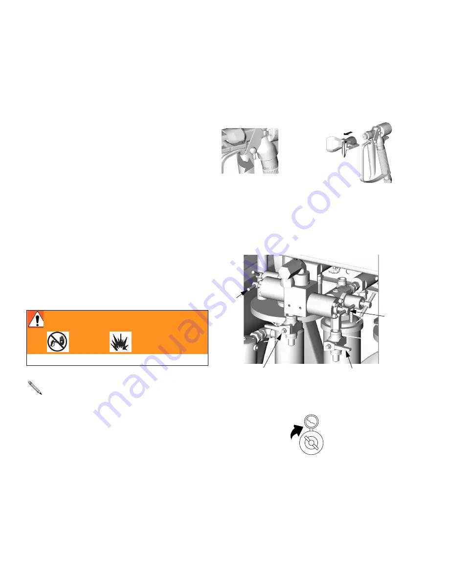
1.

Follow 

Pressure Relief Procedure

, page 14. 

Engage trigger lock. Remove spray tip. 

2.

Ensure that shutoff valves G

A

 and G

B

 are open. 

Connect solvent pump line to solvent purge valve J

A


and J

B

. Turn on solvent pump and open solvent 

purge valve J

A

.

3.

Adjust solvent pump regulator to desired pressure; 
use lowest pressure possible.

TI5183a

TI5049a

TI4957b

J

B

G

B

J

A

G

A

Summary of Contents for 234614

Page 1: ...Inc is registered to I S EN ISO 9001 310665E Operation Plural Component Proportioner Important Safety Instructions Read all warnings and instructions in this manual Save these instructions TI4912b TI...

Page 2: ...Pump Calibration Value 32 Calibrate Pump Sensor 32 Alarms 33 Performance Charts 35 Technical Data 36 Dimensions 37 Wall Mounting Diagram 37 Graco Standard Warranty 38 Graco Information 38 Manual Conv...

Page 3: ...00 carbon steel Pumps with hose and gun 4700 32 324 234616 A Cart mount HydraMix 700 carbon steel Pumps with hose and gun 4700 32 324 Heated Units 234838 A Cart mount HydraMix 700 carbon steel Pumps 2...

Page 4: ...rt mount HydraMix 700 carbon steel Pumps 480V Heaters 8 3 A each 16 6 A total with hose and gun 4700 32 324 Manual Description 310665 Xtreme Mix 185 Operation 310666 Xtreme Mix 185 Repair Parts 310654...

Page 5: ...feel a shock stop operation immediately Do not use equipment until you identify and correct the problem SKIN INJECTION HAZARD High pressure fluid from gun hose leaks or ruptured components will pierc...

Page 6: ...uids or fumes can cause serious injury or death if splashed in the eyes or on skin inhaled or swal lowed Read MSDS s to know the specific hazards of the fluids you are using Store hazardous fluid in a...

Page 7: ...internal settings Icon Function Spray proportion and spray material Run A operate A independent of B prim ing flushing for 12 cycles Run B operate B independent of A prim ing flushing for 12 cycles Ba...

Page 8: ...uipment securely to the wall Heated Units Part Nos 234838 234839 234840 and 234841 include two VISCON HP Fluid Heaters 1 Ensure that the electrical power supply meets the following requirements 2 Read...

Page 9: ...ump Air Pressure Gauge H Component A Pump J Component A Fluid Supply K Component B Pump L Component B Fluid Supply M Gun Fluid Hose N Static Mixer P Fluid Whip Hose R Airless Spray Gun S Proportioner...

Page 10: ...Component A Dispense Solenoid A opens dispense valve A The correct dose of component A flows into the mix manifold Solenoid A closes dispense valve A See FIG 4 Component B Dispense Solenoid B opens di...

Page 11: ...Installation 310665E 11 FIG 4 Fluid Mix Manifold FB OFF FB ON FB FA FA ON FA OFF HA JA GA HB GB JB M...

Page 12: ...to a true earth ground T TI4792a 2 The 50 ft 15 m fluid hose M static mixer N and whip hose P come assembled Note the order of connection 3 Connect the fluid hose M to the fluid manifold out let Do no...

Page 13: ...to air inlet 7 Set air regulator to 0 8 Open main air shutoff valve When starting up dis play will show 88888 then software revision then current ratio if set to or Air supply requirement 110 psi 0 8...

Page 14: ...tip In addition relieve pressure from pump to fluid mani fold at end of day and before cleaning checking or servicing pump manifold or fluid line accessories or transporting equipment Read warnings pa...

Page 15: ...icator A will stay on for 5 sec after Pump A reaches Park position then go off 6 Indicator B comes on and Pump B pressurizes 7 Open sampling valve B slowly to bleed off pressure Indicator B will stay...

Page 16: ...into the sys tem yet To flush the entire system you first follow the Fluid Manifold Flushing procedure at right then the Full System Flushing procedure page 20 Fluid Manifold Flushing Using Solvent P...

Page 17: ...solvent purge valve JB Flush out about 1 pint 500 cc of mixed material Engage trigger lock TI5047a TI5049a TI5048a A B JB JA 7 Re open solvent purge valve JA 8 Disengage trigger lock and flush through...

Page 18: ...Flushing 18 310665E...

Page 19: ...e into a grounded solvent pail 3 Turn pump A 3 way ball valve to open suction tube line as shown below Arrow on handle shows direc tion of flow TI5183a TI5049a Suction Tube Line A 4 Open main air shut...

Page 20: ...gger gun into a grounded pail Dispense about 1 quart 1000 cc of material 9 Close solvent purge valve JA 1 Follow Pressure Relief Procedure page 14 Engage trigger lock Set air regulator to 0 and close...

Page 21: ...rounded pail and flush until clean solvent flows from gun 16 Close solvent purge valves JA and JB 17 Follow Pressure Relief Procedure page 14 and remove gun from hose See gun manual to further clean g...

Page 22: ...r lines as shown below Arrow on handle shows direction of flow 3 Set air regulator to 0 A B 4 Close fluid shutoff valves GA and GB 5 Place a container under each sampling valve Open sampling valve HA...

Page 23: ...ess Turn up air regulator slowly until pump B starts 9 When side B is primed press Close sampling valve HB 10 Flush sampling valves HA and HB with solvent Open solvent purge valves JA and JB Turn on s...

Page 24: ...th sides 1 Turn function knob to Set air regulator to 0 Open main air shutoff valve Adjust air pressure to 50 psi 0 35 MPa 3 5 bar 2 Dispense fluid A a Close fluid shutoff valves GA and GB and sam pli...

Page 25: ...Xtreme Mix 185 Repair Manual 4 Dispense fluid B as follows a Place a clean 1 quart 1000 cc container under sampling valve HB b Slowly open and adjust sampling valve HB to achieve desired flow The pum...

Page 26: ...and HB Open shutoff valves GA and GB 3 Turn function knob to Press 4 Trigger gun into a pail and slowly increase air regula tor pressure until pump is running and consistently mixed material is dispe...

Page 27: ...n foil at typical pres sure setting flow rate and tip size until multiple changeovers of each pump have occurred Trigger and de trigger at typical intervals for the application Do not overlap or cross...

Page 28: ...s always 1 pint 500 cc of total volume regardless of ratio setting 1 Turn function knob to Set air regulator to 0 Open main air shutoff valve Adjust air pressure to 50 psi 0 35 MPa 3 5 bar 2 Dispense...

Page 29: ...Use the following information to determine approximate pot life volume PLV in cc Integrator manifold and mixer volume 75 cc Spray Gun Volume 20 cc Hose Volume x Feet of Hose 75 20 PLV Pot Life Reset V...

Page 30: ...ess To begin spraying turn function knob to reset system to desired ratio and adjust pump to spray pres sure During recirculation only the pump runs A and B dispense valves do not operate Material pum...

Page 31: ...e pages 14 and 15 Engage trigger lock 4 Before prolonged shutdown cap fluid outlets to keep solvent in the lines Fill pump A and B packing nuts and dispense valve A and B wet cups with throat seal liq...

Page 32: ...Calibrate Pump Sensor 9 Press Release first then release The pump will move up cycle to the board end of sensor first then down and stop If pump fails to move up and down within 5 sec Alarm 27 or 28...

Page 33: ...fitting or use of agitator Empty fluid supply 07 Pump Error B 08 Sensor Code Error Always Sensor values reverted to default Sensor value data corrupt board needs replacement and or recalibration 09 M...

Page 34: ...es not com pletely stall in downstroke Intake valve ball check failure 18 Inlet Ball B 19 Dispense Valve A Test Pump does not com pletely stall in both up and down strokes Throat packing or dispense v...

Page 35: ...0W oil Fluid Outlet Pressure psi MPa bar 100 psi 0 7 MPa 7 bar 70 psi 0 48 MPa 4 8 bar 40 psi 0 28 MPa 2 8 bar 4000 28 0 280 2000 14 0 140 3000 21 0 210 1000 7 0 70 5000 35 0 350 0 0 1 0 3 80 0 6 2 28...

Page 36: ...scfm at 1 gpm 1 76 m3 min at 3 8 lpm Ambient temperature range Operating 32 104 F 0 40 C Storage 30 160 F 1 71 C External Power Supply Requirements 85 250 Vac 50 60 Hz 2 amps maximum draw 15 amp maxim...

Page 37: ...et size 1 2 npt f Fluid inlet size 1 in npsm m Fluid outlet size mix manifold 3 8 npt f Weight Non heated 240 lb 108 kg Heated 330 lb 149 kg Six 0 406 in 10 3 mm diameter mounting holes 11 in 279 4 mm...

Page 38: ...rial or workmanship repairs will be made at a reasonable charge which charges may include the costs of parts labor and transportation THIS WARRANTY IS EXCLUSIVE AND IS IN LIEU OF ANY OTHER WARRANTIES...

Reviews: