background image

26

308-082

Pressure Control

WARNING

To reduce the risk of serious injury whenever you
are instructed to relieve pressure, always follow the
Pressure Relief Procedure on page 7.

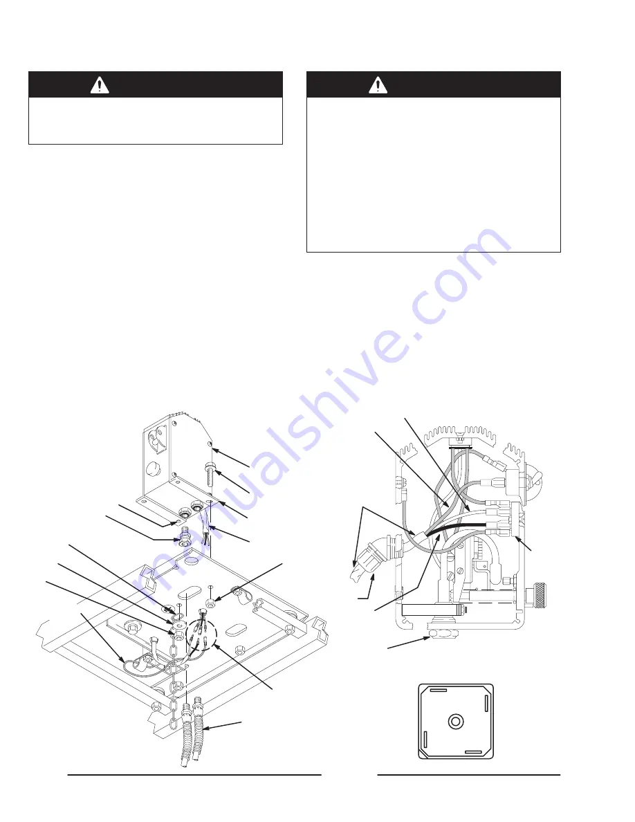
1.

Disconnect both hoses (133) at the pressure control
swivel unions (108). Note the original location of
each hose to be sure you reassemble them correctly
at the end of this procedure. See Fig. 23.

2.

Working under the engine mounting plate of the cart,
disconnect the pressure control wires at A. Remove
the four nuts (40) and related hardware from the
capscrews (91 & 87).

3.

Remove the pressure control covers (89). See Fig.
23.

4.

Disconnect the red, black and white wires from the
rectifier (307) which are sheathed with the conductor
(309). Unscrew the connector (313) from the pres-
sure control, pulling the conductor and wires out with
it. See Fig. 24.

5.

Use a wrench to hold the hex of the adapters (C)
while removing the swivel unions (108). See Fig. 24.

WARNING

To reduce the risk of electric shock, be sure all
grounding features of the pressure control are
properly assembled:

Ground wire (308) connected in pressure con-
trol.

Serrated flange capscrews to mount the pres-
sure control to the cart.

Grounding chain (106) connected by the long
pressure control mounting capscrew (87).

6.

Reassemble the pressure control in the reverse or-
der. Use the long pressure control mounting screw
(87) in hole B. From below the mounting plate (25)
assemble the grounding chain (106), washer (105)
and nut (40) to the screw. See Fig. 23.

7.

Perform the Pressure Control Adjustment on
page 27 before regular operation of the sprayer.

BLACK

RED

WHITE

307

C

RECTIFIER (307) CONNECTIONS

GROUND

BLACK

RED

WHITE

309

313

108

106

105

40

133

40

89

91,87

109

309

B

A

TO FILTER

TO PUMP

TO ENGINE

-

+

~

~

0032

0033

0034

Fig. 23

Fig. 24

Summary of Contents for 231-132

Page 1: ...GM 3500 GASOLINE POWERED AIRLESS LINESTRIPER LineLazer 3000 psi 210 bar 21 0 MPa Maximum Working Pressure Model 231 132 Series A With one gun RAC IVR DripLesst Tip guard Size 317 LineLazer Tip Size 517 SwitchTipt and 50 foot 15 m hose Model 231 140 Same as 231 132 except includes Second Gun Kit 224 097 GRACO INC P O BOX 1441 MINNEAPOLIS MN 55440 1441 Graco Inc is registered to I S EN ISO 9001 ...

Page 2: ...K Gun holder L Rac IV tip guard M Switch Tip N Flex gun O Displacementpump P Caster Q Dual gun selector cable R Pressure control S Spark plug cable T Air Cleaner U Muffler V Fuel Tank W Hook eyelet use to strap pail or pail cover to cart X Pail cover Y Caster Cable Z Grounding cable and clamp AA Collar A B C D E F G H J K L M N O P Q R S T U V W X Y Z AA 0001F ...

Page 3: ...r Lever Cable Operation 20 Operation 20 Maintenance 20 Caster Tire Replacement 20 Caster Cable Tension Adjustment 20 Caster Alignment 20 How to Mount the Gun 20 Gun Cable Dual Gun Selector Operation 21 How the Dual Gun Selector Works 21 How to Release the Selector Cable 21 Adjust the Trigger Cable Tension 22 Maintenance 23 Troubleshooting 24 Repair or Replacement Pressure Control 26 Pressure Contr...

Page 4: ...e maximum working pressure of the lowest rated system component Refer to the Technical Data on page 46 for the maximum working pressure of this equipment D Use fluids and solvents which are compatible with the equipment wetted parts Refer to the Tech nical Data section of all equipment manuals Read the fluid and solvent manufacturer s warnings D Do not use hoses to pull equipment D Route hoses awa...

Page 5: ...cking or servicing the equipment Tighten all fluid connections before operating the equipment Check the hoses tubes and couplings daily Replace worn or damaged parts immediately Do not repair high pressure couplings you must replace the entire hose Fluid hoses must have spring guards on both ends to help protect them from rupture caused by kinks or bends near the couplings TOXIC FLUID HAZARD Hazar...

Page 6: ...arting or operating the sprayer Before servicing the equipment follow the Pressure Relief Procedure on page 7 to prevent the equipment from starting unexpectedly Liquidscan be injected into the body by high pressure airless spray or leaks especially hose leaks Keep body clear of the nozzle Never stop leaks with any part of the body Drain all pressure before removing parts Avoidaccidental triggerin...

Page 7: ...part of the spray gun firmly to the side of a grounded metal pail then trigger the gun Fig 1 159 Pressure Relief Procedure WARNING INJECTION HAZARD Fluid under high pressure can be in jected through the skin and cause seri ous injury To reduce the risk of an injury from injection splashing fluid or moving parts fol low the Pressure Relief Procedure whenever you are instructed to relieve the pressu...

Page 8: ...rs This increases the risk of hazardous static electric discharge which can result in serious injury fire or explosion and property damage Whenever you flush connect the ground clamp 159 to a true earth ground Using as an outdoor striper Be sure the static chain attached to the bottom of the cart drags on the ground to help dissipate static electricity Ground the sprayer to a true earth ground if ...

Page 9: ...UTION Close the black fuel shutoff lever whenever you are transporting the sprayer to prevent fuel from flooding the engine Keep the sprayer upright and level when operating it and transporting it This prevents crankcase oil from leaking into the combustion chamber which makes startup very difficult 12 To use the wheel brake lift the brake handle A bottom rear of cart to engage the brake Lower the...

Page 10: ...e knocks or pings use a higher octane fuel Unleaded fuel minimizes combustion chamber deposits 2 Gasolines containing alcohol gasohol Do not use gasohol which contains methanol if the gasohol does not contain cosolvents and corrosion inhibi tors for methanol Even if it does contain such additives do not use the gasohol if it contains more than 5 methanol NOTE The HONDA engine warranty does not cov...

Page 11: ...iage clamps B C 5 Slide the second gun bar 404 far enough into the carriage bar that the clamp 405B engages the bar Position the clamps 405A 405B over the notches A in the carriage bar 4 and tighten the clamps NOTE For stable gun operation the second gun bar 404 has a maximum recommended extension from the carriage bar of about 11 1 4 286 mm 6 Disconnect the trigger cable from the second gun at th...

Page 12: ...13 4 Put the suction tube in a grounded pail of water or solvent 5 Remove the gun s from the holder Remove the spray tip s to prevent splashing WARNING To reduce the risk of static sparking and splashing when flushing always remove the spray tip from the gun and hold a metal part of the gun firmly to the side of and aimed into a grounded metal pail 6 Follow Startup on page 13 Keep the gun triggere...

Page 13: ...n cold weather In cold weather leave the choke closed for 10 to 30 seconds before opening it to keep the engine running 6 Release the trigger cable and engage the gun trigger safety latch See page 21 7 Remove the gun from the holder by unscrewing the gun holder knob and lifting out the gun 8 To start the pump NOTE Lower the throttle setting for easier priming a Open the pressure drain valve R b Tu...

Page 14: ... Gun Trigger Safety Latch Q Remote TriggerCable R Pressure Drain Valve S Suction Tube F G H J L M N P Q R S Shown in off position Shown off Fig 10 K 0001F 14 308 082 Startup 15 Read Spray Techniques on page 16 CAUTION Close the black fuel shutoff lever E whenever you are transporting the sprayer to prevent fuel from flooding the engine Keep the sprayer upright and level when operating it and when ...

Page 15: ... Fig 11 Place the seat E on a pencil curved side out as shown in Fig 12 Guide the seat into the retaining nut A and turn the seat until it straddles the cylinder of the spray tip F Drop in the appropriate gasket and press it down If using the red or yellow gasket C be sure the flat side faces out of the retainer A See Fig 11 Screw the spray tip guard snugly onto the gun holding it in the desired p...

Page 16: ...that many factors affect the straight ness of a line including uneven surfaces potholes rocks and other debris and a clogged or worn spray tip See page 15 for how to clear or change a spray tip 7 To minimize the effect of bumps on the spray pattern keep the spray tip guard centered with the front wheel axis 8 The spray tip size and the rate at which you move the unit affect the coating thickness G...

Page 17: ...age the trigger cable NOTE See Fig 15 Two collars F are located above and below each gun The collars can be adjusted to pro vide stops for preset spray width positions for each gun Horizontal Position of the First Gun Method 1 Disengage the trigger cable Loosen the car riage clamps B D and slide the carriage bar 4 left or right so the gun will be outside the tire path Tighten the clamps Engage the...

Page 18: ...the gun trigger safety latch See page 21 2 Loosen the arm clamp 6 and rotate the arm A back near the rear tire and then position the arm so the spray tip guard aligns with the back axle of the unit Retighten the clamp 3 Extend the carriage bar 4 or second gun bar 404 so you can easily watch the line you are painting and also to avoid running over the paint line See page 17 4 Adjust the vertical an...

Page 19: ...19 308 082 Gun Arm Positions ONE GUN CURB SINGLE LINE DOUBLE LINE OR SINGLE LINE UP TO 24 WIDE TWO GUN CURB DOUBLE LINE OR SINGLE LINE UP TO 24 WIDE SINGLE OR DOUBLE LINE SPRAYING AROUND OBSTACLES 0017A ...

Page 20: ...caster fork E Re move screw G and the tire 114a Install the new tire and the setscrews F Tighten the setscrews equally so the tire has no play in it but turns freely Caster Cable Tension Adjustment See Fig 18 1 Loosen the nut A located just outside the carriage clamp B 2 With the pin D fully engaged in the caster fork E pull back on the cable 2 to increase the cable ten sion or push it forward to ...

Page 21: ...center the selector C How to Release the Dual Gun Selector Cable WARNING The gun is remotely triggered with a dual gun selector on the handle bar To reduce the risk of an injection injury due to remotely triggering the gun by accident always disengage the trigger cable from the block before handling the gun See Fig 21 DETAIL A The gun will trigger briefly when releasing the cable Before you remove...

Page 22: ...er B and where the gun trigger touches the bar 4 To adjust the tension loosen the screw C in the block 48 Slide the block forward to increase the gap and backward to decrease the gap Tighten the screw 5 Recheck the gap and adjust as needed CAUTION Do not allow the cable 402 to rub against the outside edges of the slot H in the block 48 to prevent premature wear of the cable Rotate the block slight...

Page 23: ... ment In very dusty environments check the filter daily Replace the element as needed Replacement elements can be purchased from your local HONDA dealer Weekly Check the level of the TSL in the displace ment pump packing nut Fill the nut if necessary Keep TSL in the nut to help lubricate the pump packings See page 8 Weekly Use a grease gun to grease the zerks 32 on this unit The grease purges pivo...

Page 24: ...ntrol switch Pressure setting too low Increase pressure Displacement pump outlet filter dirty Clean filter Tip or tip filter clogged Clean tip or tip filter Displacement pump rod seized by dry paint Service pump See page NO TAG Connecting rod worn or damaged Replace connecting rod See page 28 Drive housing worn or damaged Replace drive housing See page 29 Electrical power not energizing field Chec...

Page 25: ...ove and clean the suction tube as sembly separately to prevent further clogging Large pressure drop in hose Use larger diameter hose Paint leaks into wet cup Loose wet cup Tighten wet cup just enough to stop leakage Throat packings worn or damaged Replace packings See page NO TAG Displacement rod worn or damaged Replace displacement rod See page NO TAG Spitting from gun Air in fluid pump or hose C...

Page 26: ... conductor and wires out with it See Fig 24 5 Use a wrench to hold the hex of the adapters C while removing the swivel unions 108 See Fig 24 WARNING To reduce the risk of electric shock be sure all grounding features of the pressure control are properly assembled Ground wire 308 connected in pressure con trol Serrated flange capscrews to mount the pres sure control to the cart Grounding chain 106 ...

Page 27: ...ss spray hose Part No 223 541 0 5000 psi 0 345 bar 34 5 MPa fluid filled pressure gauge Part No 102 814 New spray tip size 0 025 to 0 029 3 8 in ignition wrench or nut driver 5 gallon pail of water or mineral spirits Swivel 156 823 Nipple 162 453 Tee 104 984 Set Up 1 Follow the Pressure Relief Procedure Warning on page 7 2 Set up the system as shown in Fig 25 Set the Dead Band Pressure Differentia...

Page 28: ...con necting rod link C with high quality motor oil Liber ally pack the roller bearing B in the connecting rod assembly 79 with bearing grease 77d supplied 6 Assemble the connecting rod 79 and bearing hous ing 76 7 Clean the mating surfaces of the bearing and drive housings 8 Align the connecting rod with the crank A and care fully align the locating pins E in the drive housing 77 with the holes in...

Page 29: ...ed The gear may stay engaged in either the drive housing or the pinion housing Do not lose the thrust balls 77c and 138k located at each end of the gear cluster The balls which are heavily covered with grease usually stay in the shaft recesses but they could be dislodged If they are caught between the gears and not removed the balls will seriously damage the drive housing If the balls are not in p...

Page 30: ... more information NOTE To disassemble the pinion continue with Repair ing the Pinion below To disassemble more of the sprayer go to page 32 To reassemble the sprayer from this point skip ahead to Reassembly page 37 Step 8 Repairing the Pinion NOTE A hydraulic press is required for disassembly and reassembly if you purchase the pinion parts individually If you do not have such a press use Repair Ki...

Page 31: ... the housing 138p Fig 32 PLACEMENT OF STEEL BLOCKS AND BAR STOCK WHEN PRESSING OFF LARGE BEARING 0043 1 3 4 2 5 Round steel bar to push on shaft 138b 1 Largebearing 138d 2 Hub Steel bar stock Two steel blocks 138f 3 4 5 6 7 Hydraulic press 6 7 Press platform 4 Using a hydraulic press place pieces of steel bar stock on the inner race of the large bearing 138d and press the shaft through the hub and...

Page 32: ...maining three screws 67 4 Tap lightly on the back of the drive housing 77 with a plastic mallet to loosen the assembly D from the clutch housing 61 Pull the assembly away the ar mature 55a will come with it 5 Remove the armature from the pinion shaft 6 Remove the four socket head capscrews 157 and lockwashers 156 Install two of the screws in the threaded holes in the rotor 55b Alternately tighten ...

Page 33: ...ead Disconnect the black and white wires 58 from the field Pull the wires carefully through the grommets before removing the engine See Fig 34 and 35 3 Lift the engine carefully and place it on a work bench 4 Remove the Field and Wiring Harness Clamp and Clutch Housing as instructed on pages 34 and 35 5 Skip ahead to Reassembly page 36 Step 1 NOTE All service to the engine must be performed by an ...

Page 34: ...h housing 61 Unplug the wiring harness 58 from under the engine mounting plate Pull the field out to expose the black and white wires 58 2 Pull the caps A off the wire screws 57 in both places on the field Loosen the screws and release the wires 58 3 Skip ahead to Reassembly page 36 Step 4 Fig 36 57 58 A 70 61 62 0046 ...

Page 35: ...orking through the slot at the bottom of the clutch housing 61 2 Install two screws B of the tool A in two of the threaded holes in the clamp Tighten the screws C until the clamp comes off 3 Skip ahead to Reassembly page 36 Step 3 or continue below Clutch Housing NOTE Refer to Fig 38 1 Remove the four capscrews 156 and lock washers 157 which hold the clutch housing 61 to the engine 64 2 Remove the...

Page 36: ...ews 60 to 125 in lb 14 N m 4 Connect the wires of the harness 58 to the screws 57 in both places on the field Pull the plastic caps C up and snap them over the screws Guide the wires of the harness 58 through the slot in theclutch housing Slide the field 70 into the clutch Align the setscrew chamfers in the field and the clutch housing 61 Tighten the setscrews 62 oppositely and evenly to 25 in lb ...

Page 37: ... until the chamfered end of the hub 138 protrudes through the armature See Detail B Fig 41 There will be significant resistance Attach the cardboard spacer supplied with the clutch kit to the face of the armature Engage the tabs on the spacer with the slots in the armature Brace the cart against a wall to keep it from rolling Push the drive pinion assembly onto the clutch housing 61 There will be ...

Page 38: ...63 C Face must be clean A VIEW FROM UNDER ENGINE MOUNTING PLATE DETAIL A Torque to 15 ft lb 20 4 N m 25 70 To filter To pump 50 132 51 To field To engine 58 24 B 62 Tighten oppositely and evenly torque to 25 in lb 2 8 N m 0060 0052A 0051 1 3 4 2 55a 138f 1 Chamfered end of hub DETAIL B 2 3 4 5 5 ...

Page 39: ...ternal 2 306 100 284 NUT hex 8 32 1 308 220 979 CONDUCTOR red 2 309 220 978 CONDUCTOR red white black 1 310 100 035 SCREW mach slotted pan hd 8 32 x 312 1 311 108 783 SCREW mach flat hd 8 32 x 812 1 313 108 852 CONNECTOR 45_ 1 316 222 352 TRIAC 1 317 107 070 SCREW flat head 6 32 x 625 2 318 100 072 NUT hex 6 32 2 319 103 181 LOCKWASHER No 6 external 2 320 101 754 PLUG pipe 3 8 npt 1 BLACK RED WHIT...

Page 40: ...6 38 39 114 3 83 1 110 26 24 28 33 32 33 139 37 40 42 117 87 116 115 112 41 25 105 40 32 30 30 26 52 99 40 2 40 41 REF 3 E 86 118 See page 41 See page 44 Label 1 3 4 2 1 2 3 See page 42 4 168 169 170 171 172 Ref 13 159 150 114b 114c 114d 114e 10 114a 2 183 185 184 186 193 194 195 104 E A A ...

Page 41: ...5 100 731 WASHER 3 8 2 107 186 620 LABEL grounding 1 110 224 019 CART 1 112 224 066 CASTER LATCH ASSY Includes 1 of item 32 1 114 238 052 SWIVEL CASTER Includes items 114a 114c 1 114a 112 820 SCREW cap hex hd 1 114b 112 822 BEARING needle 1 114c 112 823 RACE needle 1 114d 112 824 SEAL 1 114e 112 825 SPRING Belleville 115 801 020 NUT 1 2 13 w nylon insert 4 116 101 044 WASHER flat 1 2 4 117 111 195...

Page 42: ...157 156 66 59 67 74 73 109 135 REF 25 40 108 REF 133 106 105 40 26 REF 133 18 111 43 14 193 Ref 2 55 56 70 77a 77b 77c 129 50 132 51 85 REF 86 17 61 58 59 104 26 59 60 155 88 107 REF 24 See page 40 Seemanual307 806 Label Located on bottom Located on inside of cover Located on outside of cover 1 3 4 2 5 6 2 2 3 1 4 1 1 5 6 0004B Ref 84 12 15 16 ...

Page 43: ... x 1 023 special 1 72 155 541 UNION 90_ 1 4 npt x 1 4 npsm swivel 1 73 107 209 SCREW mach filh 8 32 x 1 4 74 179 899 COVER drive housing 1 75 176 817 SPRING retaining 1 76 218 035 BEARING HOUSING 1 77 218 032 DRIVE HOUSING KIT Includes items 77a to 77c 1 77a 178 967 WASHER bronze 1 77b 107 089 WASHER silver 2 77c 100 069 BALL 1 78 221 042 GEAR REDUCER 1 79 218 034 CONNECTING ROD KIT 1 80 107 218 C...

Page 44: ... HOLDER gun 1 96 108 483 SCREW shoulder sch 1 4 x 3 8 1 97 181 795 JAW clamp 1 98 235 459 FLEX GUN See manual 308 235 for parts 1 99 101 345 NUT hex jam 1 4 20 2 100 108 535 BEARING sleeve 1 101 107 445 CAPSCREW sch 1 4 20 x 1 1 2 1 103 111 045 SCREW shoulder sch 5 16 x 1 1 113 LLT 317 Line Lazer Tip Sz 317 1 132 100 133 LOCKWASHER 3 8 1 136 237 859 RAC IV DripLess TIP GUARD 1 158 221 517 SwitchTi...

Page 45: ...ternal 1 138f 183 515 HUB armature 1 138g 110 607 CLUTCH roller 1 Ref No Part No Description Qty NOTE Items 138h to 138p are not included in a kit Or der them separately as needed 138h 105 684 BEARING ball roller 1 138j 107 088 BEARING ball needle 1 138k 100 069 BALL sst 1 138m 109 000 RING retaining internal 1 138n 105 489 PIN dowel 2 138p 185 491 HOUSING pinion 1 138h 138m 138a 138n 138e 138f 13...

Page 46: ...SE ONLY GENUINE GRACO PARTS AND ACCESSORIES French 185 956 Spanish 185 961 German 186 041 Greek 186 045 Korean 186 049 English 185 953 Apply other languagehere 0057 DANGER LABELS The English language DANGER label shown on page 1 is also on your sprayer If you have painters who do not read English order one of the following labels to apply to your sprayer The drawing below shows the best placement ...

Page 47: ...47 308 082 Notes ...

Page 48: ...hall be as set forth above The buyer agrees that no other remedy including but not limited to incidental or consequential damages for lost profits lost sales injury to person or prop erty or any other incidental or consequential loss shall be available Any action for breach of warranty must be brought within two 2 years of the date of sale GRACO MAKES NO WARRANTY AND DISCLAIMS ALL IMPLIED WARRANTI...

Page 49: ... man ual or keep this sheet with your manual Technical Data From Engine 4 0 Horsepower Honda To Honda GX120 Engine Power Rating 3600 rpm ANSI 4 0 Horsepower DIN 6270B DIN 6271 NA 2 1 Kw 2 8 Ps NB 2 6 Kw 3 6 Ps 17 September 98 All written and visual data contained in this document reflects the latest product information available at the time of publication Graco reserves the right to make changes a...

Reviews: