


14
308069
Maintenance
Pump packing nut adjustment
WARNING
To reduce the risk of serious injury whenever you
are instructed to relieve pressure, always follow the
Pressure Relief Procedure on page 8.
WARNING
Keep your hand and fingers away from the piston
when it is moving. As the piston moves into the
pump base it can amputate fingers or break tools
caught between the moving parts. Note the pinch
point shown in Fig. 12. Be sure all air and fluid
pressure is fully relieved before adjusting the piston
or packing nut to reduce the risk of amputation.
NOTE: Perform this adjustment if: (a) material drips
steadily from the air motor weep hole, which indicates
the packings are too loose, or (b) the pump requires
more than 35 psi (244 kPa, 2.4 bar) air pressure to
cycle when the gun is triggered, which indicates the
packings are too tight.
1.
Relieve the pressure.
2.
Remove the six screws (24) using a 1/4” nut driver.
Remove the muffler plate (20).
See Fig. 13.
3.
Check to see that the air motor piston is at the top
of the stroke. If it is not, first read the warning
above. Then, while keeping your fingers away
from moving parts, apply very low pressure air to
the air inlet to move the piston up. Close the air
regulator and disconnect the air supply hose.
Refer to Fig. 12.
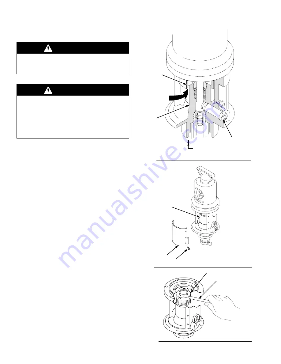
4.
Use a 1/4” diameter rod to tighten the packing nut.
First loosen the nut, then tighten snugly, and finally
tighten 1/4 turn more. See Fig. 14.
5.
Replace the muffler cover, and the six screws.
See Fig. 13.
6.
Reconnect the air line. After the pump is started, it
should run at 20 psi (1.5 bar) with no load. Startup
may require additional air pressure.
WEEP HOLE LOCATED
OPPOSITE FLUID OUTLET
AND IN BOTTOM OF BASE
Fig. 12
BASE
PISTON
PINCH POINT
FLUID
OUTLET
Fig. 13
24
20
BASE
Fig. 14
1/4” DIA. ROD
PACKING NUT


