background image

10

307851

Service (Model 204464)

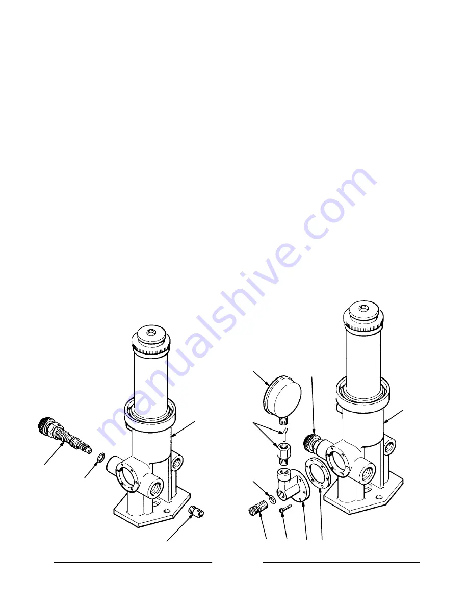
Restrictor Valve Repair

1.

Loosen the hex nut on the valve stem (6*) and
remove the stem and o-ring (14*) from the base
(20). See Fig. 4.

2.

Use a screwdriver to remove the valve seat (23).

3.

Clean and inspect all parts. Replace as necessary.
Reassemble in the reverse order of disassembly.

Fluid Pressure Gauge Repair

1.

To recalibrate the gauge (2c), adjust the valve (6)
so the gauge needle points to the first dial gradua-
tion mark above the zero stop. Refer to Fig. 5.
Turn the calibration  screw (2f) clockwise to in-
crease and counterclockwise to decrease the
setting. Do not remove the calibration screw from
the housing. Any loss of oil results in lower sensi-
tivity.

2.

If the gauge needs frequent calibration or loses
sensitivity, check the housing (2a) for oil leaks.
Connections between the gauge and housing must
be tight. If oil leaks around the calibration screw
(2f), or the screw cannot be turned inward, disas-
semble and recharge, as explained in the following
steps.

3.

To recharge the gauge, remove the six screws (8)
from the housing (2a). Clean and inspect the
diaphragm inside the housing (2a). If the housing
diaphragm has cracks or leaks, replace the hous-
ing (2a).

4.

Remove the calibration screw (2f) and inspect the
o-ring (2d*) for damage. Replace if necessary.

5.

Remove the gauge (2c) from the pulsation damp-
ener (2b) carefully, to avoid all loss. Check the
gauge with air pressure, and replace it if it is
damaged.

6.

Place the housing (2a), with its base face down, on
a flat surface. Fill the housing with light machine
oil, such as SAE 5W, through the calibration screw
(2f) opening. When nearly full, place a finger over
the gauge opening and fill the screw opening to
overflowing. Install the screw (2f) and o-ring (2d*)
until flush, then turn in two full turns.

7.

Place the housing in a vise with the gauge opening
up and fill with oil to overflowing. Using thread
sealant, tighten the gauge securely into the hous-
ing. If the gauge is fully charged, it should read 20
or 30 lb. Calibrate as explained in step 1.

Fig. 4

Fig. 5

20

23

*6

*14

2c

2b

*2d

8

2f

2a 2e*

20

6*

Summary of Contents for 204464 B Series

Page 1: ...or Pump Model 204456 Model 204722 Series C For Pump Models 206780 208177 223776 223777 218555 and 218556 Model 223953 Series A For Pump Model 223954 Instructions Parts List 307851K EN Important Safety...

Page 2: ...his equipment Use only genuine Graco parts and accessories D Check equipment daily Repair or replace worn or damaged parts immediately D Do not exceed the maximum working pressure of the lowest rated...

Page 3: ...rocedure on page 5 to prevent the equipment from starting unexpectedly FIRE AND EXPLOSION HAZARD Improper grounding poor ventilation open flames or sparks can cause a hazardous condition and result in...

Page 4: ...rate pump manual 2 Air compressor follow manufacturer s recommen dations 3 Fluid hoses use only grounded hoses with a maximum of 500 ft 150 m combined hose length to ensure grounding continuity 4 Spra...

Page 5: ...your pump has a restrictor valve close it also 2 Close the bleed type master air valve required in your system 3 Hold a metal part of the gun valve firmly to the side of a grounded metal pail and tri...

Page 6: ...om the rod refer to the piston detail in Fig 2 Use a pliers D on the air exhaust plate 15e and a wrench C on the piston rod 14 5 Remove the three capscrews 15a and disas semble the piston 15 Clean all...

Page 7: ...e 15c 15f 15b 15g 15d 15a 220168 AIR VALVE AND PISTON ASSEMBLY 15 13 3 12 4 MOTOR CAP AND CYLINDER 6 14 5 7 2 9 PISTON ROD AND BASE 11 15 A B PISTON DETAIL 15e 6 14 C D 0 032 in 0 8 mm minimum 1 2 App...

Page 8: ...r to the piston detail in Fig 3 Use a pliers D on the air exhaust plate 1e and a wrench C on the piston rod 3 5 Remove the three capscrews 1a and disas semble the piston 1 Clean all parts in a compat...

Page 9: ...2 7 PISTON ROD AND BASE MOTOR CAP AND CYLINDER 1 A B 17 3 5 15 11 21 20 1e 1c 1f 1b 1g 1d 1a 220168 AIR VALVE AND PISTON ASSEMBLY 1 PISTON DETAIL 1e 17 3 C D 0 032 in 0 8 mm minimum 22 1 2 Torque to 1...

Page 10: ...s semble and recharge as explained in the following steps 3 To recharge the gauge remove the six screws 8 from the housing 2a Clean and inspect the diaphragm inside the housing 2a If the housing diaph...

Page 11: ...rubber 1 9 161770 BASE air motor 1 10 16J475 HOUSING connecting rod 1 11 16J720 RING connecting 1 12 162989 GASKET neoprene rubber 1 13 204465 CAP air motor 1 14 24J678 ROD piston 1 Ref No Part No Des...

Page 12: ...12 307851 Parts Model 204464 5 15 11 22 21 1e 1c 1b 1d 23 25 26 20 8 17 16 18 3 12 7 6 14 2c PART OF ITEM 2 2b 2e 2a 2d 2f 1 2 1a 1g 1f 1 2 Torque to 10 14 in lb 1 3 1 6 NSm Apply sealant 1 2...

Page 13: ...T diaphragm vellumoid 1 2d 158293 SCREW calibration 1 2e 157127 GASKET diaphragm vellumoid 1 2f 158293 SCREW calibration 1 3 219091 TUBE displacement 1 Ref No Part No Description Qty 5 204465 CAP air...

Page 14: ...a Maximum Inbound Air Pressure 180 psi 1 25 MPa 12 5 bar Air Inlet Size 1 4 npt f Effective Piston Area 1 6 sq in 10 cm2 Effective Piston Diameter 1 4 in 35 2 mm Stroke Length Models 204464 204722 4 i...

Page 15: ...15 307851 Notes...

Page 16: ...s shall be available Any action for breach of warranty must be brought within two 2 years of the date of sale GRACO MAKES NO WARRANTY AND DISCLAIMS ALL IMPLIED WARRANTIES OF MERCHANTABILITY AND FITNES...

Reviews: