Installation
3A5266D
11
Divider Valves
1.
Check for valve operation by
-
using a performance indicator (shows that the
valve has cycled),
-
or, checking for lubricant dispensing at each
lube point.
2.
Adjust the injector output if needed to ensure that
the output volume discharged is sufficient.
Pressure Relief Valve
Adjustment
The pressure relief valve is factory set to 4000 psi
(275.8 bar, 27.6 MPa) for grease models and 1000 psi
(68.95 bar, 6.89 MPa) for oil models.
The relief point may require adjustment in systems that
have components that are rated higher or lower than the
factory presets.
Do not
exceed 4000 psi (275.8 bar,
27.6 MPa) in either grease or oil systems.
To adjust the pressure relief
valve, turn the pressure
adjustment screw (a) clock-
wise to increase the pres-
sure relief point or
counter-clockwise to
decrease the pressure relief
point.
Whenever the valve is
set/adjusted (after the set
point is found) it is important
to ensure that the valve is not bottomed out and there is
at least 1/2 turn of adjustment remaining. This is deter-
mined by turning the screw (a) 1/2 turn and then back
turning it out again.
Pressure Relief Procedure
Follow the Pressure Relief Procedure whenever
you see this symbol.
1.
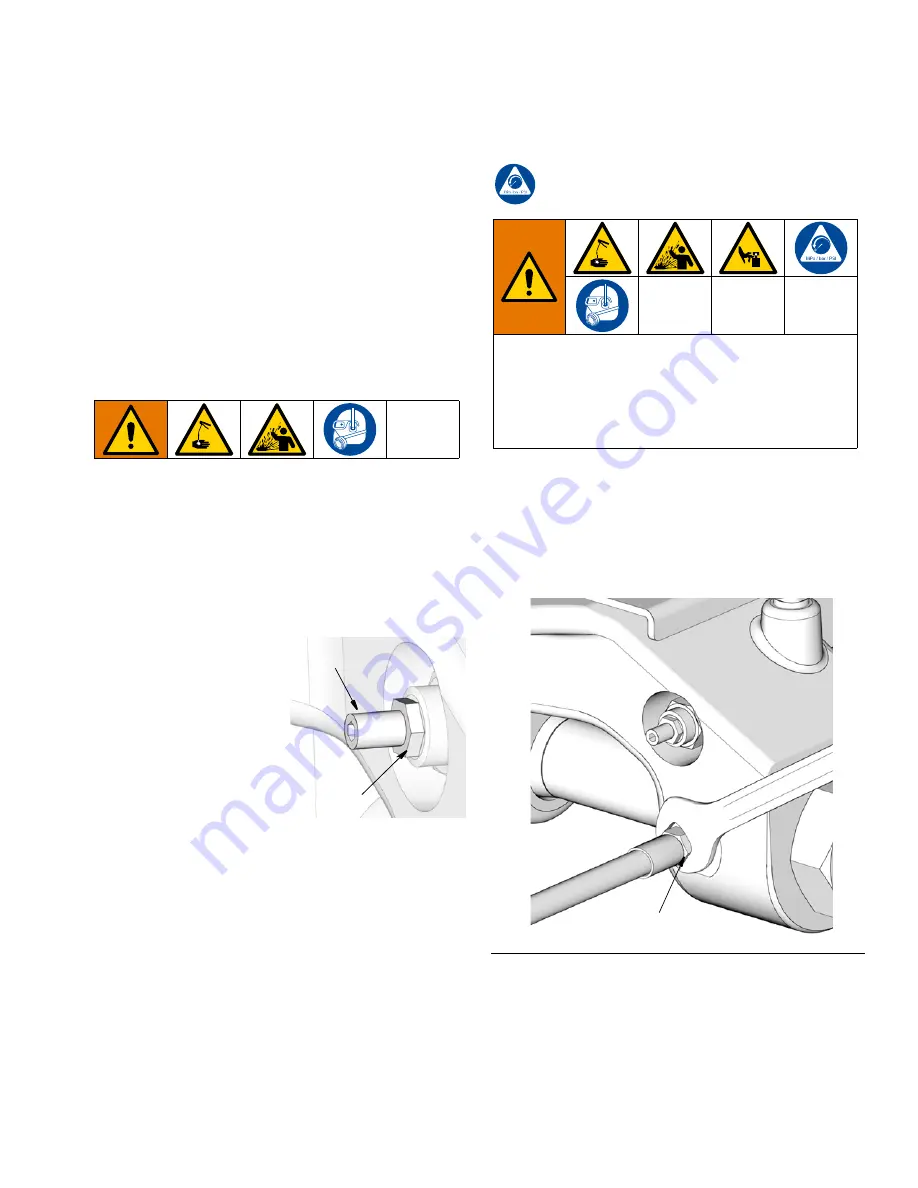
Close the bleed-type master air valve (F, page 5)
(required in the system).
2.
To
relieve pressure in the system use a wrench to
slowly loosen
the lubrication line fitting (G) until no
lubricant or air is leaking out of the fitting (F
IG
. 10).
a
locking
nut
This equipment stays pressurized until pressure is
manually relieved. To help prevent serious injury from
pressurized fluid, such as skin injection, splashing
fluid and moving parts, follow the Pressure Relief Pro-
cedure when you stop dispensing and before clean-
ing, checking, or servicing the equipment.
F
IG
. 10
G


