background image

3

Grounding Methods

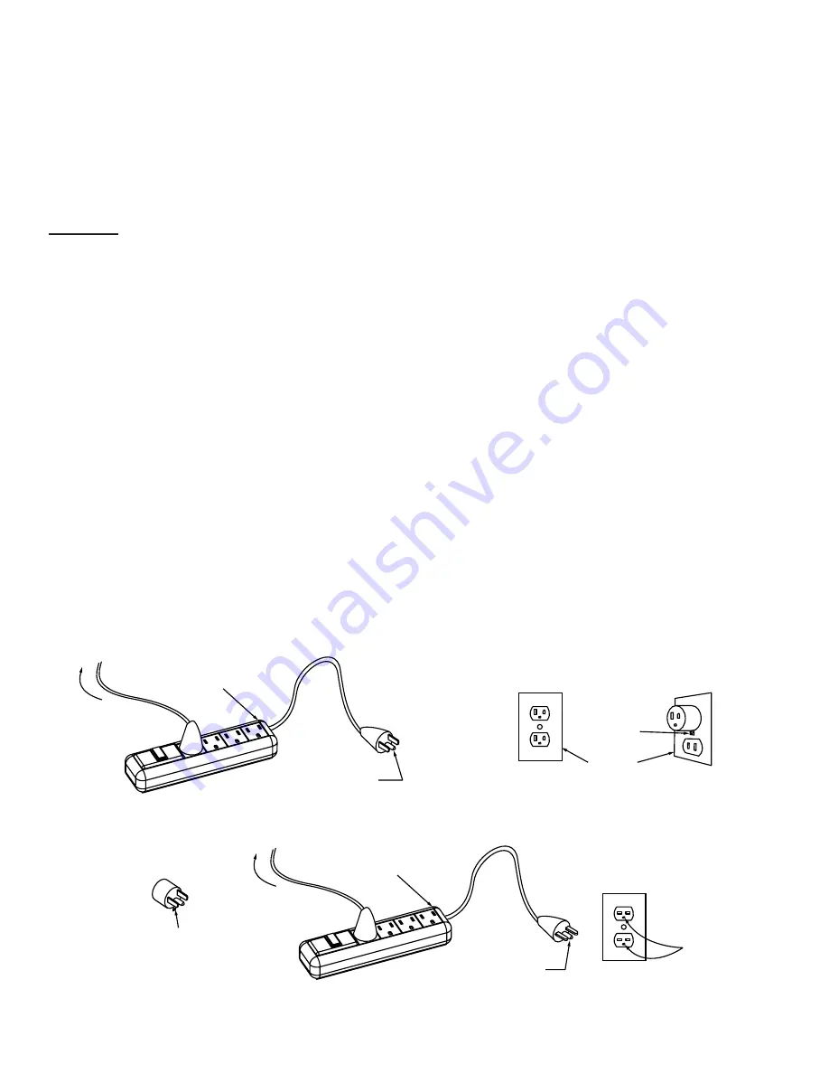
Figure 61.1

(B)

Cover of 

Grounded 

Outlet Box

Metal 

Screw

(A)

Grounding 

Pin

Surge 

Protector

To Sewing 

Machine

(C)

Adapter

Grounding 

Means

(D)

Grounding 

Pin

Surge 

Protector

To Sewing 

Machine

Grounding 

Conductor 

IMPORTANT SAFETY INSTRUCTIONS

GROUNDING INSTRUCTIONS

This product must be grounded. In the event of malfunction or breakdown, grounding provides a path 

of least resistance for electric current to reduce the risk of electric shock. This product is equipped 

with a cord that has an equipment-grounding conductor and a grounding plug. Plug the cord from 

the Quilting Machine into a surge protector.  The surge protector must be plugged into an appropriate 

outlet that is properly installed and grounded in accordance with all local codes and ordinances.

DANGER

 - Improper connection of the equipment-grounding conductor can result in a risk of electric 

shock. The conductor with insulation having an outer surface that is green with or without yellow 

stripes is the equipment-grounding conductor. If repair or replacement of the cord or plug is necessary, 

do not connect the equipment-grounding conductor to a live terminal. Check with a qualified electrician 

or serviceman if the grounding instructions are not completely understood, or if in doubt as to whether 

the product is properly grounded.

Do not modify the plug provided with the product - if it will not fit the outlet, have a proper outlet 

installed by a qualified electrician.″

This product is for use on a nominal 120 V circuit, and has a grounding plug that looks like the plug 

illustrated in sketch A in Figure 61.1. A temporary adapter, which looks like the adapter illustrated in 

sketches B and C, may be used to connect this plug to a 2-pole receptacle as shown in sketch B if a 

properly grounded outlet is not available. The temporary adapter should be used only until a properly 

grounded outlet can be installed by a qualified electrician. The green colored rigid ear, lug, and the like, 

extending from the adapter must be connected to a permanent ground such as a properly grounded 

outlet box cover. Whenever the adapter is used, it must be held in place by the metal screw. 

A qualified electrician should be consulted if there is any doubt as to whether an outlet box is properly 

grounded.

Summary of Contents for Q'nique 15

Page 1: ...Copyright December 17 2018 Grace Company Reproduction Prohibited Version 3 4 ...

Page 2: ... air openings blocked Keep ventilation openings of the Quilting Machine free from the accumulation of lint dust and loose cloth 5 Never drop or insert any object into any opening 6 Do not use outdoors 7 Do not operate where aerosol spray products are being used or where oxygen is being administered 8 To disconnect turn all controls to the off position then remove the plug from the outlet 9 Do not ...

Page 3: ...cement of the cord or plug is necessary do not connect the equipment grounding conductor to a live terminal Check with a qualified electrician or serviceman if the grounding instructions are not completely understood or if in doubt as to whether the product is properly grounded Do not modify the plug provided with the product if it will not fit the outlet have a proper outlet installed by a qualif...

Page 4: ...ng Machine 15 Winding The Bobbin 19 Installing The Bobbin Case 21 Adjusting Thread Tension 22 Thread Tension 23 Plugging In The Cables 24 Final Checklist 25 Sewing Basic Controls 26 Main Menu 27 Sewing Modes 28 Tools Menu 30 Maintenance Repair Kit 33 Replacing The Encoder Spring 34 The Needle Plate 35 The Hook Holder 36 Hopping Foot 37 Timing The Machine 39 Changing A Needle 41 Oiling The Machine ...

Page 5: ...Minimum SPM 90 8 Input Voltage 110 220 VAC 9 Peak Power Consumption 300 W 10 Timing Belt System 11 Bobbin Type Large M Class 12 OLED Screen 13 Custom Ergonomic Handles and Handlebars for efficiency and extended use 14 Built in Bobbin Winder 15 Dual Thread Tension Guides for precise tension Technical Data Specifications And Overview Front Right Left Rear ...

Page 6: ...Cutter 5 Bobbin Wind Stand 6 Bobbin Sensor 7 Dual Thread Tension Guide 8 Small Thread Tensioner 9 Large Thread Tensioner 10 Thread Guides 11 Take Up Lever 12 Lamp 13 Needle Bar 14 Needle 15 Hopping Foot 16 Thread Stand 17 Carriage wheels 18 Hand Wheel 19 Bobbin Case 19 10 1 3 11 6 13 4 15 9 5 7 12 18 2 16 8 14 17 ...

Page 7: ... Lower Encoder Black Spring Bobbin 3 one in bag Power Cord Oil Bottle M3 Thumb Screw Needle Screw Upper Encoder Spring Silver Lower Encoder Spring Black 3mm T handle Allen Wrench 4mm T handle Allen Wrench 2 5mm T handle Allen Wrench 2mm T handle Allen Wrench Flat Head Screw Driver Encoder O Ring 2 Thread Mast Upper Encoder Silver Spring Zip Tie 2 Zip Tie Mount 2 Hopping Foot Height Gauge ...

Page 8: ...s on the machine Note Estimate the distance the wheels need to be moved to sit on your carriage and set the machine onto the carriage on your quilting frame Parts Tools Needed 3mm T handle Allen Wrench Single Track Bracket M6 Set Screw Double Track Bracket M6 Set Screw Dual Track Single Vertical Track ...

Page 9: ...while centering the machine between the left and right wheels Tighten the Set Screws using the 3mm Allen Wrench Parts Tools Needed 3mm T handle Allen Wrench Single Vertical Track Double Single Track Adaptor Height Spacer Dual Track Adaptor ...

Page 10: ...that they contain all of the necessary parts and that the Lock Collar is loose 4mm T Handle Allen Wrench Upper Encoder Silver Spring Lower Encoder Black Spring 2mm T Handle Allen Wrench Parts Tools Needed Orientation Diagram Shoulder Spacer Washer Wheel Spacer Plastic Stop M6 x 16mm SBHCS Wheel Lock Collar Front Right Left Rear The Encoders must be installed in the left rear position of the top an...

Page 11: ...o the rear left position of the Bottom Carriage 4 Twist the Lock Collar on the Lower Encoder up to tighten the Spring Tighten the Set Screw using the 2mm Allen Wrench to tension the Encoder Lower Encoder Black Spring Lower Encoder Black Spring Upper Encoder Silver Spring Upper Encoder Silver Spring Upper Encoder Silver Spring Wheel Lower Encoder Black Spring Wheel Twist Lock Collar up Tighten the ...

Page 12: ...g Machine The Longer Cable is used for the Encoder attached to the carriage while the Shorter Cable is used for the Encoder attached to the Quilting Machine 4 Secure the Long Encoder Cable to the side of the Carriage using a Zip Tie and Mount Parts Tools Needed Long Encoder Cable Short Encoder Cable Zip Tie 2 Zip Tie Mount 2 Long Encoder Cable Short Encoder Cable Zip Tie and Mount Single Wheel Dua...

Page 13: ...ng it on Note The Guide Loops on the Thread Mast should be positioned so that they are directly above the Thread Stands Parts Tools Needed Thread Mast The Thread Mast acts as a guide for the thread and makes it less likely to get snagged or looped around any object Thread Mast Guide Loops Thread Mast Base Thread Stand ...

Page 14: ...LED Screen with Cable 1 Connect the Display Ribbon Cable from the Display to the Display Hub and attach the Display by snapping it into the Display Hub Connecting Front Display Display Ribbon Cable Display Screen Display Hub ...

Page 15: ...ead Tensioner 5 Large Thread Tensioner 6 Thread Guide 7 Right Thread Guide 8 Take up Lever 9 Left Thread Guide 10 Bottom Thread Guide 11 Eyelet of Needle 12 Eye of Needle 1 2 3 4 5 6 7 8 9 10 11 12 11 12 3 5 Needle Diagram Scarf Eye Point Shaft Shank Front View Side View Groove ...

Page 16: ...Thread Tensioner between the two Disks 3 Put the thread through the top hole on the Dual Thread Tension Guide wrap the thread around and through the bottom hole of Thread Guide 1 Place thread on the cone style Thread Stand Dual Thread Tension Guide Thread Cone Small Thread Tensioner Thread Mast Thread Stand Guide Loop ...

Page 17: ... Take Up Lever 5 Loop the thread down around the Large Thread Tensioner and pull the thread through the Tensioner Disks and around the Check Spring 6 Feed thread through Thread Guide next to Large Thread Tensioner Check Spring Right Thread Guide Take Up Lever Large Thread Tensioner Thread Guide Large Thread Tensioner ...

Page 18: ...10 Pull the thread down towards the Needle and through the Bottom Thread Guide 11 Feed the thread through the Eyelet in the front of the Needle Bar 12 Feed the thread through the Eye of the Needle Left Thread Guide Bottom Thread Guide Needle Bar Eyelet Eye of the Needle ...

Page 19: ...Cam into the Bobbin Parts Tools Needed Bobbin Note When the Bobbin is full it will automatically stop 2 The Bobbin winds in a clockwise direction Thread Mast 1 3 4 5 6 Push Bobbin Winder Cam Make sure the thread is between the Tensioner Disks Adjust the cam so that the Bobbin does not over fill Thread Cutter The Bobbin Winder runs on a separate motor from the Quilting Machine This allows you to wi...

Page 20: ... thread through both holes in the Bob bin Thread Guide 4 Wrap the thread around the Bobbin as shown 5 Start the Bobbin Winder by pushing the Bob bin Winder Cam into the Bobbin Note When the Bobbin is full it will automatically stop Adjust the Cam to adjust bobbin fill Thread Mast Push Bobbin Winder Cam Bobbin Thread Tensioner Bobbin Thread Guide Spring Hook Guide Loop ...

Page 21: ...nto the Quilting Ma chine with the lever arm at the 3 o clock posi tion and press it into place until it clicks in Note the direction the thread is coming off the Bobbin in relation to the Bobbin Case Bobbin Case Hook Assembly Bobbin Case Bobbin Pull Several Inches Of Thread Out Of The Bobbin Case Pull the Lever To Release The Bobbin Case Do Not Use The Lever when Inserting The Bobbin Case Slot ...

Page 22: ...s not pull the Bob bin vertical the tension is too loose and will need to be tightened 2 To adjust the bobbin tension locate the larger of the two screws on the bobbin case Tighten the tension in minute adjustments by twisting the large screw to the right or clockwise To loosen twist the large screw to the left or counterclock wise in small increments 3 Adjust the top thread tension after the bob ...

Page 23: ...ounterclockwise If the top thread is being pulled through the bottom layer of fabric you need to increase the tension on the top thread by turning the top tension knob clockwise If the thread is properly tensioned the top thread and the bobbin thread will knot in the middle of the fabric layers A thread tension tutorial is availablie on our website at http www qniquequilter com videos tutorials QR...

Page 24: ...to begin sewing turn on the machine using the power switch located on the back of the machine Below is a reference of how the machine should be configured Encoder Encoder Foot Pedal Quilt Motion Control USB Connector Port On Power Adapter Power Cord Quilt Motion Tablet Short Encoder Cable Long Encoder cable For sit down system Programming only For optional Automation Accessory Off ...

Page 25: ...andle Bars are not loose The Display Hub is secured to the Handle Bars The Display powers on and displays the quilting settings Check for bent Needles The Needle is secured firmly to the Needle Bar The Power Cord is securely connected No objects other than quilting materials should be near the Needle or quilting area of the Quilting Machine Before you begin sewing make sure that ...

Page 26: ...late manual or baste this button will cause the Quilting Machine to sew or stop sewing 5 Increase Scroll up When in a menu this button will scroll up for navigation of listed icon selections When a variable window is highlighted such as speed stitches per inch time or cycles this button will allow the user to increment the value of the variable up 6 Decrease Scroll down When in a menu this button ...

Page 27: ...t Manual Mode This mode allows you to set the speed of the machine When sewing in this mode the machine speed is fixed To get consistent stitch lengths you must adjust your movements to match the speed of the machine This mode is especially useful for small continuous stippling type patterns as opposed to regulated stitching functions Baste The baste feature allow the user to place a temporary sti...

Page 28: ... allow the machine to regulate Needle Position Indicator This is a visual representation for the default needle position when sewing is stopped To change hold the left needle up down button for three seconds SPI Setting Stitch Per Inch Shows the current SPI setting the minimum is 4 and the maximum is 16 Start Stop Indicator This button indicates what action the Quilting Machine will take when the ...

Page 29: ...he baste stitch can be set to small medium or large The Speed indicator shows current sewing speed as a percentage of the maximum 1800 stitches per minute The minimum being 5 and the maximum of 100 Stitch Size Setting Speed Setting Indicator ...

Page 30: ...s of the machine to identify issues Stitch Time This screen displays the number of stitches sewn and hours the machine has run Hours and stitches can be reset individually To reset either one navigate to the option you wish to reset using the or keys and then press select Total This area cannot be reset The Quilting Machine will keep track of the total number of stitches sewn and hours the machine...

Page 31: ...ware version Diagnostics The diagnostics are used to identify where the Quilting Machine may be experiencing an issue This will be very useful when working with a technician The diagnostics can be used to troubleshoot a machine They provide a means to do testing should a problem arise Motor Control Firmware Version Number Display Control Firmware Version Number Motor Control Firmware Version Date ...

Page 32: ...nu Continued Preferences This screen will be used to change defaults for various options as follows Default Precise Cruise Baste Menu Units Inches Metric Inches Baste Small Medium Large Stitch Inch 4 16 Over Speed On Off Left Handed Right Handed This will reverse the buttons for right or left handed users ...

Page 33: ... 1 A replacement for the needle bar set screw Encoder Springs 1 Black 1 Silver Replacement springs for the encoders Timing Spacer 1 A tool to make timing your machine easier and more consistent If the thumb screw is overtightened it will strip out and will need to be replaced If the encoder springs are over tensioned the may break and must be replaced Hopping Foot Height Gauge 1 A tool to set the ...

Page 34: ...om the encoder then remove the broken encoder spring 3 Put the replacement spring on the encoder Set the Long Spring Arm in the hole on the Lock Collar and set the Short Spring Arm in the hole on the Encoder Base 4 Replace the Washer Wheel Spacer and Plastic Stop then reattach the encoder to the carriage Replacing The Encoder Spring Parts Tools Needed Lock Collar Encoder Spring Washer Wheel Spacer...

Page 35: ...iddle of the Needle Plate without contacting the Needle Plate at any point 2 Attach your Needle Plate using 4 Needle Plate Screws don t tighten the screws during this step 3 Rotate hand wheel until the Needle is in the lowest position move Needle Plate till it is centered around Needle and tighten all 4 Needle Plate Screws Flat Head Screw Driver Parts Tools Needed Needle Plate Needle Plate Screw N...

Page 36: ...e of the Hook Assembly s Posi tioning Guide The Hook Holder Tools Needed 3mm T Handle Allen Wrench 3 Slide your Hook Holder away from the Hook Assembly so there is about a 0 75mm gap it s hard to measure so just make it as big of a gap as possible between the Hook Holder and the Hook Assembly and tighten the M5 X 10mm FHCS Hook Assembly 0 75mm Gap between Hook Holder and Hook Assembly Hook Assembl...

Page 37: ... until the Needle Bar is in the lowest position 2 Attach your Hopping Foot to the press bar using a M3 Thumb Screw don t tighten during this step Hopping Foot Tools Needed 3mm T Handle Allen Wrench Hopping Foot Height Gauge M3 Thumb Screw Press Bar Needle Plate Hopping Foot ...

Page 38: ...he Hopping Foot so that is centered 4 Place the Hopping Foot Height Gauge under the Hopping Foot and make sure the Hopping Foot is touching the Hopping Foot Height Gauge Tighten the M3 Thumb Screw using the 3mm Allen Wrench Hopping Foot Height Gauge ...

Page 39: ...nch by inserting the wrench into the machines Timing Hole Cut Out as each Set Screw aligns with the hole 3 Rotate the Hand Wheel clockwise from the front of the machine so Needle is raising out of the Hook Assembly Note Consult with technical support before attempting to adjust the machine timing Hook Assembly Needle Set Screws Hook Scarf 0 02 0 1mm Gap Needle ...

Page 40: ... the hook by watching to see if the Needle bends during rotation and there is no clicking noise Rotate machine Hand Wheel a full rotation to ensure the Needle doesn t hit anywhere during rotation If Needle hits the Hook Assembly anywhere during rotation adjust needle height up or down off center from Hook in 0 25mm increments as appropriate to clear the collision Tighten the two remaining Set Scre...

Page 41: ...turn 4 Remove Old Needle and insert the New Needle 5 Hand tighten the Thumb Screw while holding the Needle in place The eye of the needle faces the bobbin opening New Needle Needle Thumb Screw Old Needle Needle Thumb Screw Hand tighten Needle Thumb Screw only Be sure to install the Needle with the scarf indent toward the throat of your machine ...

Page 42: ...te Lint build up between the Tension Disks can prevent you from being able to properly tension your thread 1 Remove the Bobbin Case Tools Needed Lint Brush Oil Bottle Oiling The Machine Separate the Tension Disks and clear them of lint and debris Separate the Tension Disks and clear them of lint and debris Bobbin Case ...

Page 43: ... ensure all components receive lubrication Note The head of the machine and the Hook Assembly are the only areas that require regular lubrication Frequency Once every other Bobbin change 1 Remove the Bobbin Case 2 Ensure all lint and thread remnants have been removed 3 Rotate the Hand Wheel so that the Needle is halfway down about a quarter turn This will put the hook in the optimal position to be...

Page 44: ...e bobbin the Tension Disks Post will need to be lowered by twisting the Post Clockwise and retightening the hex nut 2b If thread winds mostly on the bottom of the bobbin the Tension Disks Post will need to be heightened by twisting the Post Counter Clockwise and retightening the hex nut Tools Needed 1 5mm Allen Wrench not included 9mm Crescent Wrench not included Set Screw Note Production 1 has on...

Reviews: