Brother 083-8775, Instruction Manual
The Brother 083-8775 Instruction Manual is a comprehensive guide for maximizing the potential of your product. This user-friendly manual is available for free download from manualshive.com, ensuring that you have access to all the essential information needed to optimize your experience with Brother 083-8775.
Share
Download


Reviews:
No comments
Related manuals for 083-8775

Terra 3700B
Brand: Advance acoustic Pages: 64

PLH-981
Brand: JUKI Pages: 2

BINDPRO
Brand: National Flooring Equipment Pages: 36
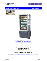
Snakky 6-27R/F
Brand: Necta Pages: 23

PHANTOM F3
Brand: Cameo Pages: 40

ibico clickman
Brand: GBC Pages: 10

STAC Vision 1.5
Brand: Zeck Audio Pages: 15

Aria BLAR
Brand: Baby Lock Pages: 200

550-19-2
Brand: Duerkopp Adler Pages: 9

PRESTO
Brand: Baby Lock Pages: 128

DDL-9000B-DS
Brand: JUKI Pages: 8

DDL-9000C-F Series
Brand: JUKI Pages: 138

DH4-B980
Brand: Brother Pages: 66

EF4-B641
Brand: Brother Pages: 56

DB2-B797
Brand: Brother Pages: 2

DB2-B797
Brand: Brother Pages: 28

DB2-B773-003
Brand: Brother Pages: 67

DB2-B773
Brand: Brother Pages: 21


