background image

page 13

Infrared Wireless Remote Control Operation

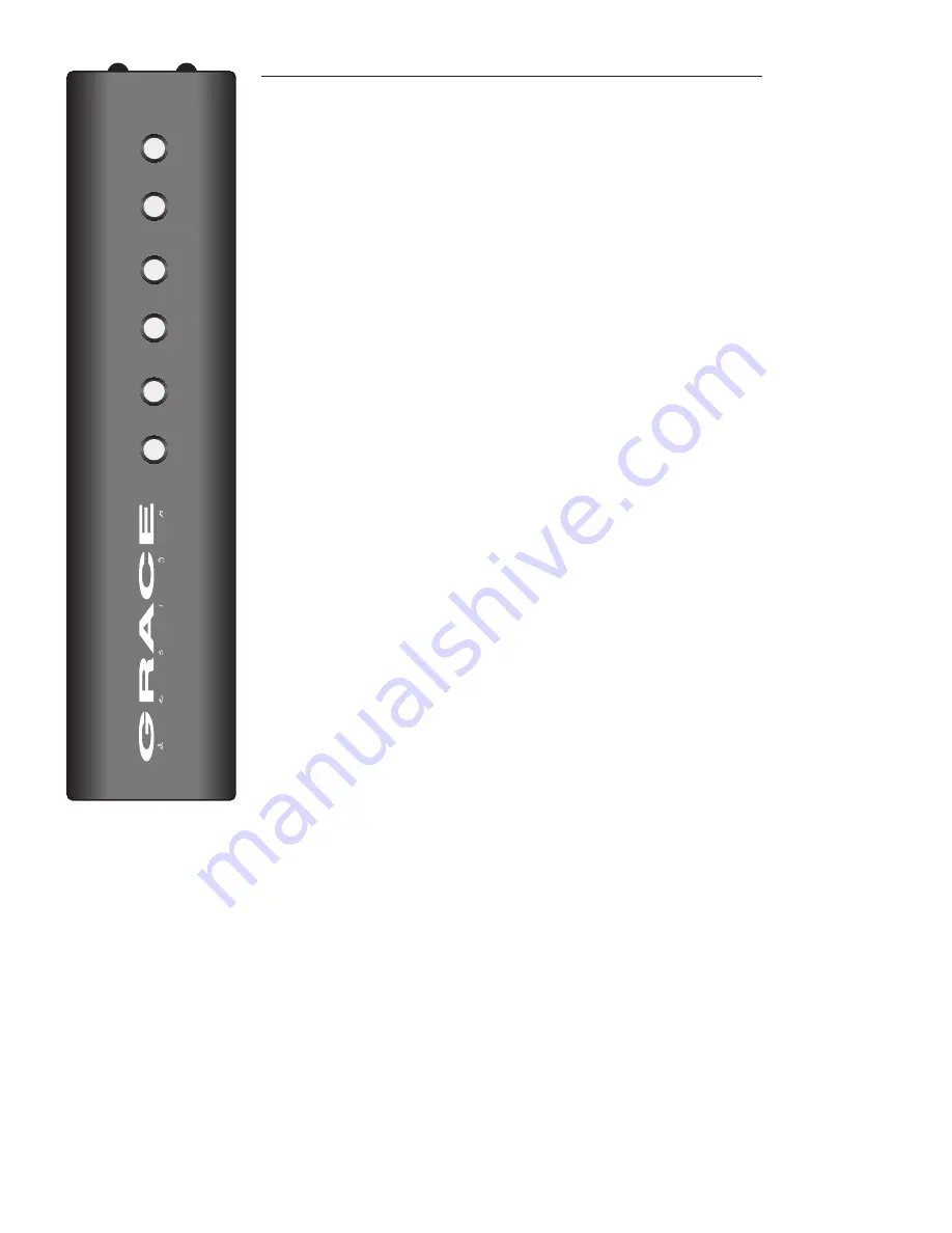
A optional high quality wireless remote control is available as a very convenient control for the 

m903. The following section details all of the features available from the remote control. Several 

of the buttons on the remote have dual functions, accessed by either a ‘push’ or a ‘push and hold’ 

action, and are described below. To activate an m903 for use with a remote control please refer to 

the ‘infrared remote control enable’ procedure in the ‘accessing and using the setup menu’ chapter 

of this manual. The factory default setting is active

MUTE (PUSH)

 - Pushing and releasing this button toggles the mute setting for the currently se-

lected output on the m903. Once engaged, active mute status will be reflected by the 7-segment 

display flashing on and off in regular intervals.
To disable muting simply press the mute button again. The output will return to the current level 

setting and the display will return to solid.
In addition to pushing the mute button, mute can be turned off by making any volume change 

(on remote control or on the m903 itself).

MUTE

 (PUSH AND HOLD)

 Pushing and holding the mute button will toggle the exclusive output 

(EO) setting and will exit you from the submenu mode. The current exclusive output status will be 

displayed momentarily on the m903 display.

X-FEED (PUSH)

  - Pushing this button toggles the x-feed status on the m903. The current x-feed 

status will be displayed momentarily on the m903 7-segment display, as well as by the dedicated 

x-feed LED to the right of the volume control. Also, pressing the x-feed button while in the setup 

menu will return the m903 to normal operation.

PHONES/LINE (PUSH)

 - Pushing and releasing this button during normal operation toggles be-

tween the 3 available outputs (phones, line 1 and line2). The newly selected output indicator LED 

will illuminate and its corresponding level will be displayed on the 7-segment display. 

PHONES/LINE


(PUSH AND HOLD)

 – Pushing and holding this button enters the m903 setup 

menu. From here you can control the setup menu in the same way as from the front panel volume 

encoder, only with the volume up / volume down buttons used to scroll, and a single push of the 

PHONES/LINE button serving as the ‘enter’ switch. Please refer back to the previous chapter  ‘ac-

cessing and using the setup menu’  for detailed information on how to navigate the setup menu.
Pushing and holding the PHONES/LINE button again will store all changes made and exit the 

setup menu.

BALANCE

 - Pushing this button will directly enter balance mode option. From here, pushing the 

volume up button will adjust the left (vol down) and right (vol up) balance. Conversely,  pushing 

the volume down button will adjust the right (vol down) and left (vol up) balance. These changes 

are indicated by the right or left facing speaker symbol changing to the corresponding balance 

offset value. Please refer back to the previous chapter ‘accessing and using the setup menu’ for a 

more detailed description of adjusting the balance setting.
Pressing this button while the m903 is in balance mode will exit the user from the sub-menu and balance mode.

BALANCE (PUSH AND HOLD)

 – Pushing and holding the balance button during normal operation will toggle the MONO mode 

feature of the m903. This setting simply sums the left and right channels of all outputs together. When MONO mode is active, the 

7-segment display no longer displays the current output level numbers and shows two large facing brackets. Pushing and hold-

ing again returns the m903 to normal stereo operation, as indicated by the brackets changing back to the current output level 

numbers.

VOLUME UP / VOLUME DOWN

 -  In normal operation pressing the volume up or down buttons will change the selected m903 

output level respectively in 0.5dB steps.  Also, pressing the volume up or down buttons while the selected output is muted will 

unmute the output. NOTE: Pushing and holding the Volume up / down buttons results in continuous volume changes.  The longer 

a button is held the quicker the volume level changes.
If the setup menu has been entered by pushing and holding the PHONES/LINE button, the volume up and down buttons are used 

to scroll through the available setup menu items.

MUTE

X-FEED

PHONES/

LINE

BALANCE

VOL


VOL


Summary of Contents for m903

Page 1: ...Owner s Manual Rev A all contents Grace Design Lunatec LLC 2434 30th Street Boulder CO 80301 USA www gracedesign com 303 443 7454 m903 reference headphone amplifier DAC monitor controller ...

Page 2: ...r website www gracedesign com for the latest Grace Design product information owner s manuals and technical documents Grace Design has been building audiophile quality products since 1995 The technology developed for the m903 has evolved through a process of extensive listening field testing and careful refinement Regardless of what type of moni toring you do your m903 will faithfully serve as an ...

Page 3: ...e and transportation temperature range 40 C to 70 C Maximum altitude 3000m 9843 ft Equipment suitable for continuous operation Weight 2 3kg 5lbs Safety Marking Symbols CAUTION READ ACCOMPANYING DOCUMENTS This symbol located on the equipment and in this manual refers to important instructions Read this manual thor oughly before operating this equipment WARNING ELECTRICAL SHOCK HAZARD This symbol lo...

Page 4: ...no electrolytic capacitors in the signal path Sealed gold contact relays are used for all signal switching Infrared remote control for level control left right balance mute and more when using the optional remote control unit 5 Year transferable warranty on parts and labor m903 Frontpanel Controls Features 1 ILLUMINATED POWER SWITCH illuminates green when unit is powered on 2 ROTARY INPUT SELECTOR...

Page 5: ...ng contact your grace design dealer and they will make sure you re taken care of Save your box We strongly encourage you to save the box and shipping materials supplied with your m903 They are specially designed to properly protect these valuable components and in the unlikely event that you need to return them for service only these OEM shipping materials can ensure their safe return to our facto...

Page 6: ... carrier with the proper line voltage showing through the small window Note that time delay or slow blow fuses are required Voltage and Fuse information CAM SETTING LINEVOLTAGE FUSEVALUE 110V 100 120V 250V T 250mA L 220V 220 240V 250V T 125mA L AC power cord Connect the supplied AC cord to the iec power entry module on the rear panel of the m903 For safety it is recommended that the cable be conne...

Page 7: ...Sleeve jacks These outputs are wired in parallel Connection to headphones should be made using standard TRS stereo connectors UNBALANCED LINE OUTPUTS A stereo pair of unbalanced line level outputs are provided via two RCA jacks These outputs should be connected to powered speakers or power amplifiers using standard unbalanced RCA cables BALANCED LINE OUTPUTS A stereo pair of balanced line level ou...

Page 8: ... that as your audio playback device and the system will work Different operating systems may pose their own set of complications in setting up the m903 as the audio playback device In the event that plug and play operation does not occur you will need to look at some specific setup variables for your OS In this case we will direct you to a very well written and comprehensive document by our friend...

Page 9: ...time delay compared to the right ear As well the right speaker sound that reaches the left ear does not have a flat frequency response as the sound waves have traveled around the shape of your head before reaching your left ear The brain uses delay level and frequency response characteristics to process the location of a sound and hence create an aural image When listening through headphones each ...

Page 10: ... settings in non volatile memory and recalls these upon each power up Power Up Level This feature allows the user to save specific level settings for each output as the default power up level While default levels are set to 0 at the factory you may want to have the unit always power up at a specified level other than the default To program power up level settings 1 Push and hold the rotary encoder...

Page 11: ...ng off 3 Rotate the encoder to navigate to other setup menu items or push and hold to exit the setup menu Display dimmer mode The m903 features bright user interface designed to give you clear operational information However situations may exist when you want to turn off this display while keeping your unit running This is possible with the display dimmer mode With the display dimmer enabled all t...

Page 12: ...ontrol of two different sets of monitors mains and nearfields One interesting possibility for having the two line outputs grouped is a simple 2 1 monitoring setup send one set to your moni tors and the other to a subwoofer Use the level offset feature to trim either set of outputs accordingly To select between the two line output modes 1 Push and hold the rotary encoder to enter the setup menu The...

Page 13: ...ere you can control the setup menu in the same way as from the front panel volume encoder only with the volume up volume down buttons used to scroll and a single push of the PHONES LINE button serving as the enter switch Please refer back to the previous chapter ac cessing and using the setup menu for detailed information on how to navigate the setup menu Pushing and holding the PHONES LINE button...

Page 14: ... RX S PDIF INPUT TOSLINK INPUT s Lock PLL CLOCK AUDIO 24 bit 192kHz USB module INPUT SELECT INPUT SELECT CROSSFEED LINE OUTPUT LEVEL CONTROL HEADPHONE OUTPUT LEVEL CONTROL UNBALANCED ANALOG OUTPUT CROSSFEED ENABLE TRANSIMPEDANCE HEADPHONE AMPLIFIER Master clock MONO LINE OUTPUT LEVEL CONTROL 2 CHANNEL line 2 BALANCED LINE OUTPUT AMPLIFIER BALANCED ANALOG OUTPUT BALANCE LEVEL MUTE ANALOG INPUTS DIG...

Page 15: ...ne Out 116dB THD N Balanced Input Headphone Out 10dBu 50 Ohm load SMPTE 4 1 0 020 Headphone Out 10dBu 50 Ohm load 0 0060 Unbalanced Line Out 10dBu 100k Ohm load 0 00026 Balanced Line Out 20dBu 100k Ohm load 0 00036 Attenuator Channel matching 0 05dB Attenuator Range 97 5dB Output Noise Floor Balanced Input Balanced Output volume at maximum 22 22kHz 90dBu Balanced Output volume at minimum 22 22kHz ...

Page 16: ...ce at its option any defective parts or repair defective workmanship without charge provided the customer has appropriate proof of purchase and that the product has its origi nal factory serial number 4 In order for Grace Design to provide efficient and timely warranty service it is important that you mail the completed warranty registration card enclosed with all of our products within 10 days of...

Page 17: ...page 17 Manual Revisions Revision Page Change Date Initials A Initial release 12 20 2010 edg ...

Reviews: