GORMAN-RUPP 13D1-(19) PPO Installation, Operation And Maintenance Manual Download Page 18

OM−05463

10 SERIES

TROUBLESHOOTING

PAGE D − 3

PREVENTIVE MAINTENANCE

Since pump applications are seldom identical, and
pump wear is directly affected by such things as
the abrasive qualities, pressure and temperature
of the liquid being pumped, this section is intended
only to provide general recommendations and
practices for preventive maintenance. Regardless
of the application however, following a routine pre-
ventive maintenance schedule will help assure
trouble-free performance and long life from your
Gorman-Rupp pump. For specific questions con-
cerning your application, contact your Gorman-
Rupp distributor or the Gorman-Rupp Company.

Record keeping is an essential component of a
good preventive maintenance program. Changes
in suction and discharge gauge readings (if so

equipped) between regularly scheduled inspec-
tions can indicate problems that can be corrected
before system damage or catastrophic failure oc-
curs. The appearance of wearing parts should also
be documented at each inspection for comparison
as well. Also, if records indicate that a certain part
(such as the seal) fails at approximately the same
duty cycle, the part can be checked and replaced
before failure occurs, reducing unscheduled down
time.

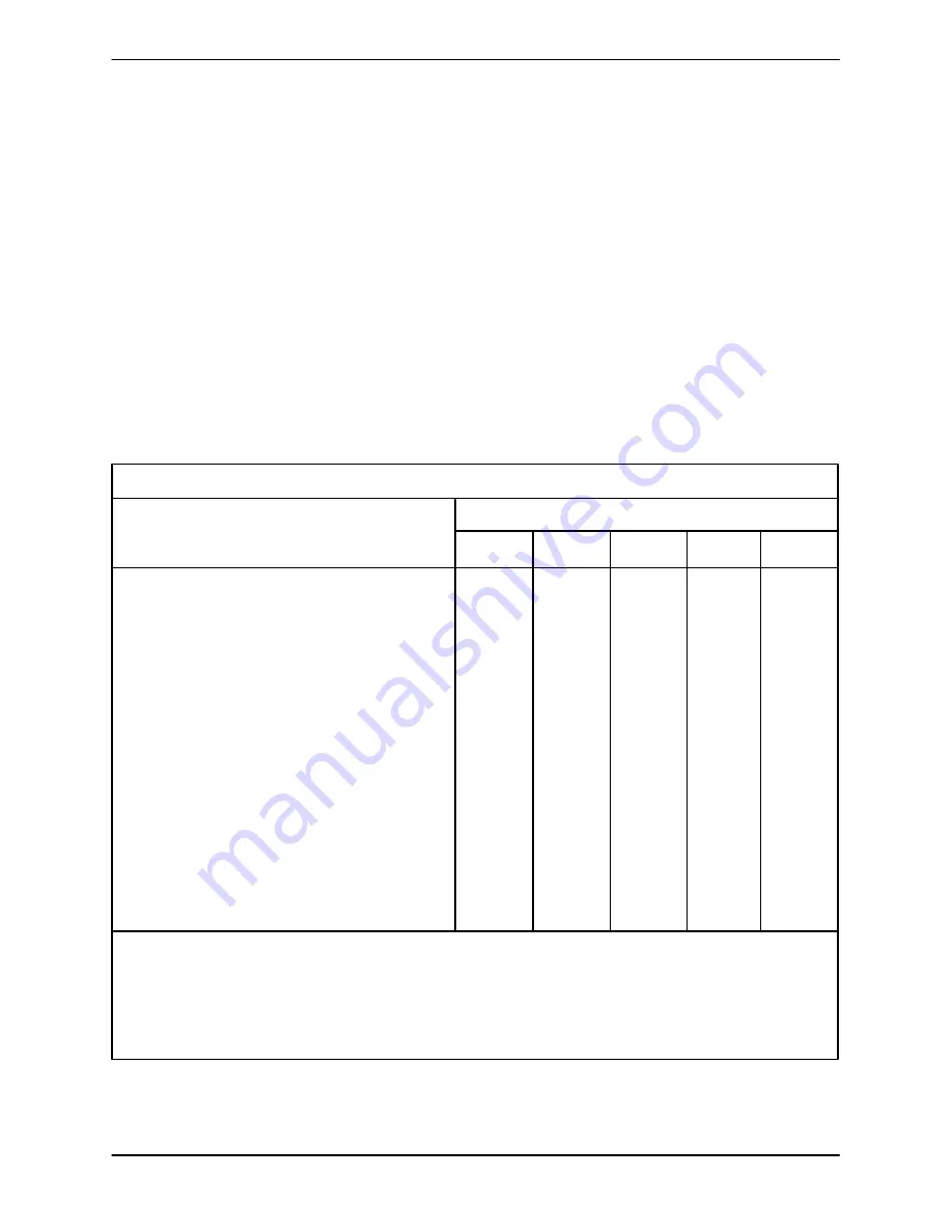
For new applications, a first inspection of wearing
parts at 250 hours will give insight into the wear rate
for your particular application. Subsequent inspec-
tions should be performed at the intervals shown
on the chart below. Critical applications should be
inspected more frequently.

General Condition (Temperature, Unusual

Noises or Vibrations, Cracks, Leaks,
Loose Hardware, Etc.)

I

Pump Performance (Gauges, Speed, Flow)

I

Bearing Lubrication

I

R

Seal Lubrication (And Packing  Adjustment,

If So Equipped)

I

R

V-Belts (If So Equipped)

I

Air Release Valve Plunger Rod (If So Equipped)

I

C

Front Impeller Clearance (Wear Plate)

I

Rear Impeller Clearance (Seal Plate)

I

Check Valve

I

Pressure Relief Valve (If So Equipped)

C

Pump and Driver Alignment

I

Shaft Deflection

I

Bearings

I

Bearing Housing

I

Piping

I

Driver Lubrication − See Mfgr’s Literature

Legend:
 I = Inspect, Clean, Adjust, Repair or Replace as Necessary
C = Clean
R = Replace

* Service interval based on an intermittent duty cycle equal to approximately 4000 hours annually.

Adjust schedule as required for lower or higher duty cycles or extreme operating conditions.

Preventive Maintenance Schedule

Item

Daily

Weekly

Monthly

Semi-

Annually

Annually

Service Interval*

Summary of Contents for 13D1-(19) PPO

Page 1: ...MANSFIELD OHIO GORMAN RUPP OF CANADA LIMITED D ST THOMAS ONTARIO CANADA Printed in U S A www gormanrupp com ECopyright by the Gorman Rupp Company INSTALLATION OPERATION AND MAINTENANCE MANUAL WITH PA...

Page 2: ...The engine exhaust from this product contains chemicals known to the State of California to cause cancer birth defects or other reproductive harm...

Page 3: ...B 3 Sealing PAGE B 3 Suction Lines In Sumps PAGE B 3 Suction Line Positioning PAGE B 4 DISCHARGE LINES PAGE B 4 Siphoning PAGE B 4 Valves PAGE B 4 Bypass Lines PAGE B 5 OPERATION SECTION C PAGE C 1 PR...

Page 4: ...mp Casing Removal PAGE E 7 Impeller Removal PAGE E 7 Seal Removal and Disassembly PAGE E 7 Seal Reassembly and Installation PAGE E 7 Impeller Installation And Adjustment PAGE E 9 Pump Casing Installat...

Page 5: ...write The Gorman Rupp Company or Gorman Rupp of Canada Limited P O Box 1217 70 Burwell Road Mansfield Ohio 44901 1217 St Thomas Ontario N5P 3R7 For information or technical assistance on the engine c...

Page 6: ...ent the pump slowly and cau tiously 7 Drain the pump This pump is designed to handle dirty water containing specified entrained solids Do not attempt to pump volatile corrosive or flammable liquids wh...

Page 7: ...or less tasteless and odorless Fuel used by internal combustion en gines presents an extreme explosion and fire hazard Make certain that all fuel lines are securely connected and free of leaks Never r...

Page 8: ...upplied to the pump is critical to performance and safety be sure to limit the incoming pressure to 50 of the maximum permissible operating pressure as shown on the pump performance curve see Sec tion...

Page 9: ...such as suc tion and discharge piping must be removed before attempting to lift The pump assembly can be seriously damaged if the cables or chains used to lift and move the unit are improperly wrapped...

Page 10: ...ets will be created Fittings Suction lines should be the same size as the pump inlet If reducers are used in suction lines they should be the eccentric type and should be in stalled with the flat part...

Page 11: ...minimum submergence vs veloc ity NOTE The pipe submergence required may be reduced by installing a standard pipe increaser fitting at the end of the suction line The larger opening size will reduce th...

Page 12: ...rge head gradually close the discharge throttling valve before stopping the pump Bypass Lines If a system check valve is used due to high dis charge head it may be necessary to vent trapped air from t...

Page 13: ...ing The pump will not prime when dry Extended operation of a dry pump will destroy the seal assembly Add liquid to the pump casing when 1 The pump is being put into service for the first time 2 The pu...

Page 14: ...ode If overheating occurs stop the pump and allow it to cool before servicing it Refill the pump casing with cool liquid Do not remove plates covers gauges pipe plugs or fittings from an over heated p...

Page 15: ...ation In below freezing conditions drain the pump to prevent damage from freezing Also clean out any solids by flushing with a hose Operate the pump for approximately one minute this will remove any r...

Page 16: ...liquid in casing Add liquid to casing See PRIMING Suction check valve contaminated or damaged Clean or replace check valve OM 05463 10 SERIES TROUBLESHOOTING PAGE D 1 TROUBLESHOOTING SECTION D Review...

Page 17: ...clean if neces sary Pump speed too high Check driver output check that sheaves or couplings are correctly sized Suction check valve or foot valve clogged or binding Clean valve Suction lift or dischar...

Page 18: ...ly the same duty cycle the part can be checked and replaced before failure occurs reducing unscheduled down time For new applications a first inspection of wearing parts at 250 hours will give insight...

Page 19: ...nstallations are seldom identical your performance may be dif ferent due to such factors as viscosity specific gravity elevation temperature and impeller trim If your pump serial number is followed by...

Page 20: ...10 SERIES OM 05463 MAINTENANCE REPAIR PAGE E 2 SECTION DRAWING PARTSPAGE Figure 1 Pump Model 13D1 19...

Page 21: ...TTON 19 ENGINE 29122 162 1 3 ROLLOVER BASE 41583 315 24150 1 4 RUBBER FOOT MTG KIT 48152 603 1 5 HEX HD CAPSCREW B0504 15991 4 6 FLAT WASHER K05 15991 4 7 RUBBER FOOT S1224 4 8 FLANGED HEX NUT 21765 3...

Page 22: ...10 SERIES OM 05463 MAINTENANCE REPAIR PAGE E 4 SECTION DRAWING Figure 2 13D1 19 Pump Parts Only...

Page 23: ...NUT D08 15991 2 19 HEX HD CAPSCREW B0605 15991 4 20 LOCKWASHER J06 15991 4 21 INTERMEDIATE O RING 25152 248 1 22 WEAR PLATE 2643B 15990 1 23 CASING DRAIN PLUG P06 15079 1 24 LOCKWASHER J04 15991 2 25...

Page 24: ...erature supplied with the engine or contact your local Honda engine representative Before attempting to open or service the pump 1 Familiarize yourself with this man ual 2 Shut down the engine and ta...

Page 25: ...tionary portion of the seal off the shaft as a unit Use a suitably sized dowel to press the stationary element out of the in termediate from the back side NOTE The seal assembly may be removed without...

Page 26: ...O ring 21 lubricate the O ring with water or a very small amount of oil Install the O ring on the intermediate Position the intermediate against the engine bell housing and secure it with hardware 19...

Page 27: ...he pump casing to ease future dis assembly and to reduce rust and scale build up Replace the back cover gasket 33 and slide the back cover assembly 29 into the pump casing Be sure the wear plate does...

Page 28: ...hall repair or replace the defective product or part at its option without charge You must have properly installed maintained and used the product or part claimed to be defective in accordance with th...

Reviews: