background image

- 1 -

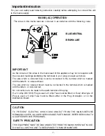
BLUE-NEUTRAL

BROWN-LIVE

CAUTION

TO  PREVENT  ELECTRIC  SHOCK  DISCONNECT  FROM  THE  MAINS  BEFORE

REMOVING COVER. NO USER SERVICEABLE PARTS INSIDE. REFER SERVICING TO

QUALIFIED SERVICE PERSONNEL.

 SAFETY PRECAUTION

THIS EQUIPMENT MUST BE DISCONNECTED FROM THE MAINS WHEN NOT IN USE.

DO NOT ALLOW THIS UNIT TO BE EXPOSED TO RAIN OR MOISTURE.

MAINS (AC) OPERATION

The wires in this mains lead are coloured in accordance with the following code :

IMPORTANT

As the colours of the wires in the mains lead of this appliance may not correspond with

the coloured markings identifying the terminals in your plug, proceed as follows:
The  wire  which  is  coloured  blue  must  be  connected  to  the  terminal  which  is  marked

with the letter N or coloured black.
The  wire  which  is  coloured  brown  must  be  connected  to  the  terminal  which  is  marked

with the letter L or coloured red.
No connection is to be made to the earth terminal of the plug.
If a 13 Amp (BS 1363) Plug is used a 5 Amp Fuse must be fitted, or if any other type of

Plug  is  used  a  5  Amp  Fuse  must  be  fitted,  either  in  the  Plug  of  Adaptor,  or  on  the

Distribution  Board.

Important Instruction

For your own safety read following instruction carefully before attempting to connect this unit

to the mains supply.

Summary of Contents for GTV69W4

Page 1: ...Goodmans Colour Television Model GTV69W4 Helpline no 0239 2391100 User Guide AK37...

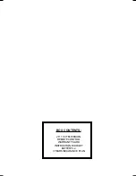
Page 2: ...BOX CONTENTS 28 16 9 TELEVISION REMOTE CONTROL WARRANTY CARD INSTRUCTION BOOKLET BATTERY x 2 3 YEARS INSURANCE PLAN...

Page 3: ...rrespond with the coloured markings identifying the terminals in your plug proceed as follows The wire which is coloured blue must be connected to the terminal which is marked with the letter N or col...

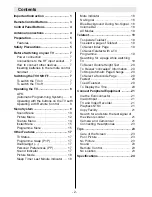
Page 4: ...nes 23 Tips 23 Care of the Screen 23 Poor Picture 23 No Picture 23 Sound 23 Remote Control 23 No solution 23 Specifications 24 Important Instruction 1 Remote Control Buttons 3 Control Panel Buttons 4...

Page 5: ...e Up Cursor Up Cursor Right VOL VOL Volume Volume Yellow FEATURE Feature Menu Blue INSTALL Installation Menu External Source AV1 AV2 FAV BAV RGB SVHS Teletext Update Hold Index Page Reveal Expand Time...

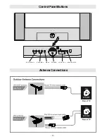
Page 6: ...4 ControlPanelButtons AntennaConnections 3 0 18 5 6 9 6 92 80 352 5 0 0 18 32 5 5217 9 3 21...

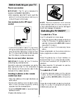
Page 7: ...a 230 240 V AC 50 Hz outlet Ensure you select the correct voltage setting for your convenience 2 Power Cord The power supply cord should be placed so that it is not likely to be walked on or pinched...

Page 8: ...such as foil bag must be kept away from children Batteries including those which are heavy metal free should not be disposed of with household waste Please dispose of used batteries in an environmenta...

Page 9: ...set by gently pulling upwards from the indicated part Insert two MN2400 AAA or equivalent type batteries inside Replace the battery cover NOTE Remove batteries from remote control handset when it is n...

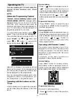
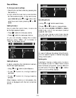
Page 10: ...setting and programme selection can be made using the buttons on the front panel Volume Setting Press button to decrease volume or button to increase volume so a volume level scale slider will be dis...

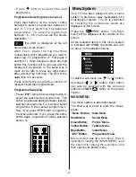
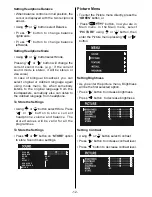
Page 11: ...ogrammes For example select programme 8 then select programme 2 Now if you press P P button programme 8 will be selected If you press the same button again programme 2 will be selected and so on MenuS...

Page 12: ...lance Press button to change balance rightward Press button to change balance leftward When balance control is in mid position the cursor is displayed with the two reciprocal arrows 92 80 1 9 7 3 21 6...

Page 13: ...ted by the user The 5 items below the MODE are available t o a d j u s t t h e s o u n d s e t t i n g s i n 5 frequency values 120 Hz 500 Hz 1 5 kHz 5 kHz and 10 kHz To change the values of 5 frequen...

Page 14: ...ed language from headphone To Store the Settings Using or button select Store Press or button to store current headphone volume and balance The stored values will be valid for all the programmes To St...

Page 15: ...16 9 This option forces the picture ratio to 16 9 mode 14 9 This option forces the picture ratio to 14 9 mode Cinema This option forces the picture ratio to Cinema mode Subtitle This option forces th...

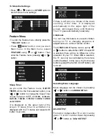
Page 16: ...only one minute of the down counting of the timer it is displayed automatically on the upper right of the screen and stayed there until finishing Then TV goes automatically to stand by Child Lock You...

Page 17: ...nce the process is stopped or signal is found During search process the semi transparent menu background becomes BLUE To stop the search process or button must be pressed again Selecting Fine Tuning Y...

Page 18: ...to blank on the selected name To change that letter or button can be used and to select the other letters or button can be used If the cursor is at the last letter of the Programme Name pressing butto...

Page 19: ...ayed with them too They are displayed after programme change during 3 seconds Programme Number Programme Name 5 characters These OSD s are displayed when a new programme is entered by digit button by...

Page 20: ...to the preceding value and the second one is increasing the volume level thus it starts at the minimum level to increase By decreasing the volume level in mute state mute will not be ignored only the...

Page 21: ...Teletext Press the appropriate digit buttons for the required Teletext page number The selected page number is displayed at the top left corner of the screen The Teletext page counter searches until...

Page 22: ...buttons e g 0001 If the selected subcode page is not displayed in a short time press button TV programme will be displayed on the screen Teletext page number will be displayed on the upper left corne...

Page 23: ...hen press 9 button to select AV1 or AV2 or FAV BAV Copy Facility Source selection for VCR recording Select Features Menu in the Main Menu Select AV 2 OUTPUT source pressing or button Search for and st...

Page 24: ...22 28 REAR PANEL ConnectPeripheralEquipment 7 7 17 8 5 9 2 287 17 11 6FDUW 6FDUW DFN 9 2XW FOR SATELLITE RECEIVER VIDEO HEADPHONE AUDIO 17 1 CAMERA...

Page 25: ...he peripherals No Picture Is the aerial connected properly Are the plugs connected tightly to the aerial socket Is the aerial cable damaged Are suitable plugs used to connect the aerial If you are in...

Page 26: ...CABLE TV S1 S20 S21 S41 NUMBEROFPRESETCHANNELS 100 CHANNELINDICATOR On Screen Display RFAERIALINPUT 75 Ohm unbalanced OPERATINGVOLTAGE 230 240 V AC 50 Hz AUDIOOUTPUT Nicam Stereo AUDIO OUTPUT POWER W...

Reviews: