background image

ENGLISH - 18

• AERIAL SOCKET [O]

This socket is on the rear television cover.
- It is used for the INPUT of the RF signal to the television.
- You can connect the following equipment to it: a)- The plug of your aerial; b)- Videorecorder.

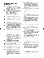
• SCART 1 [N] and SCART 2# [O] PERITELEVISION SOCKETS

These sockets are on the rear television cover.
- They are used for the OUTPUT/ INPUT of the sound/video signal from and to the television.
- You can connect the following equipment to them: a)- Videorecorder; b)- Video camera; c)- Console
for video games; d)- Digital decoder for satellite; e)- Set Top Box for Internet; f) DVD player (and so on).

6.3 - B) SELECT THE CORRECT SCART OR AV CHANNEL

Once you have connected the equipment with their cables, to receive the sound/video signal on the
screen you have to indicate to the television which specific socket you have connected the equipment
to. The 3 choices described below  can also be made by pressing key [23] on the remote repeatedly
until you see the acronym corresponding to the socket to which the equipment is connected, according
to the following.

• Choose the “AV-1” mode to see the signal coming from the SCART 1 [N] SOCKET or from the

VIDEO# [G] and AUDIO L/R# [H and I] CINCH SOCKETS.

— Note: In models where the front sockets are on the same AV channel as the SCART 1 socket, choo-
sing "AV-1" selects both SCART 1 and front CINCH inputs.
–– Note: Seeing as SCART 1 [N] peritelevision socket is also enabled to receive an RGB video signal,
if the external equipment has a video signal of this kind, you must make an additional choice in the
Set-up sub menu as follows:
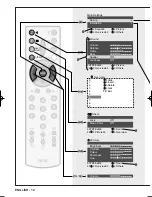
• Please refer to key numbers illustrated on the front fold-out REMOTE KEYS page.
-01- 
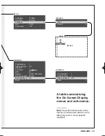
Press key [9] to see the Main Settings menu.
-02- Press key [14] to scroll the menu until you reach the “Set-up” function and confirm your choice by

pressing key [15]: the Set-up menu appears on the screen.

-03- Press key [14] to scroll the menu until you reach the “AV1” function and choose option “RGB” with

key [15 or 16]. If the external equipment is sending a normal video signal to the socket then
choose the option “CVBS” with key [15 or 16].

• Choose the “AV-2”# mode to see the signal coming from the SCART 2# [N]

 SOCKET 

In some models the front sockets are on a separate AV channel, so it will be "AV-2".

For the remaining sockets the settings and optional choices must be made in other ways.
Here is what you have to do:

• With key [13 or 14] choose a programme between 0 and 99 to view the signal coming from the

AERIAL SOCKET [M]. Alternatively you can tap in the number wanted on the numerical keypad
[21].

–– Note: If you have to connect a video recorder to this socket, to see the picture on the screen you
will have to tune and store the sound/video signal as described in paragraph 4.2 - MANUALLY FIND-
ING AND STORING STATIONS. In this case set number “0” in the “Programme” function and number
“36” (or the number specified in the video recorder instruction booklet) in the “Channel” function.

• SOCKET FOR HEADPHONES [L]: when you connect headphones to this socket, sound is no

longer heard from the television speakers but sent only through the headphones. This means that
the possible headphone sound settings are the same as those made for the television loudspeaker
sound (see paragraph 5.2 - ADJUSTING SPEAKER SOUND).

Testo del man. SWING (UK)  14-10-2002  9:41  Pagina 18

Summary of Contents for 1495T-IB

Page 1: ...COLOUR TELEVISIONS OPERATING INSTRUCTIONS 1790T 1495T IB 14 14 17 17...

Page 2: ...television off in stand by 2 12 Switching the television off automatically 2 13 Switching the television off definitely PART THREE The television s Operating System 3 1 On Screen Display 3 2 Choosing...

Page 3: ...the REMOTE CONTROL KEYS page More detail is given in section 3 2 page 10 GENERAL NOTES IMPORTANT This instruction booklet is written to cover a family of similar models but some of the func tions desc...

Page 4: ...F 2 1 5 6 9 10 13 16 17 18 21 22 3 4 8 7 12 11 15 14 20 19 23 1 3 2 4 6 5 7 9 8 0 SF 10 S P P P PIP TV AV help others over view I II P F MENU 2 1 5 6 9 10 13 16 17 18 21 22 3 4 8 7 12 11 15 14 20 19...

Page 5: ...down 14 or any number key 21 13 In the TV mode it recalls the next pro gramme number going up in order In the OSD mode it selects the next function from the menus moving up In the TXT mode it calls th...

Page 6: ...e or decreases the setting on the adjustment bar E In the Stand By mode it turns the television on In the TV mode it increases the volume of sound If the OSD button has been pressed it recalls the pro...

Page 7: ...tak ing the plug P out of the mains and disconnecting the aerial plug Q If there is an accidental overload of the electricity the television switches off automatically going in the standby mode To sw...

Page 8: ...receptacles full of water or other liquids on top of the television because if they accidentally tip over the liquid pouring through the ventilation slots can cause serious damage fire or electric sh...

Page 9: ...to what it was previously 2 10 TO USE TELETEXT If the channel you are tuned to broadcasts teletext to see it press key 1 on the remote and then tap in the number three digits of the page you want with...

Page 10: ...GUAGE FOR THE OSD Before reading any further you might wish to change the on screen menu language if is not your prefer red one Please choose a different language as follows 01 Press the MENU key 9 to...

Page 11: ...ant to tune the stations manually one at a time proceed as follows 01 Press key 9 to see the Main Settings menu 02 Press key 14 to scroll the menu until you reach Installation and confirm your choice...

Page 12: ...V Exit Sound Picture Overview Sound Volume Balance Treble Bass Spatial Off Loudness Off TV Exit Picture Overview Others Overview 0 Hide 1 Insert 2 Delete 3 Lock 4 TV Exit 5 6 7 8 9 Picture Brightness...

Page 13: ...ne Tune AFC On System AUTO PAL BG Dual Language Dual I Extended Menu On Store Installation Prog Number 1 Channel Type 1 Extended Menu Off Store Busy 0 1 OK 2 OK 3 OK 4 TV Exit 5 6 7 8 9 A table summar...

Page 14: ...nt them from being watched by an unsuitable public children for example Please refer to key numbers illustrated on the front fold out REMOTE KEYS page These operations are done in the Overview menu th...

Page 15: ...done at any time irrespective of phase B B Locking The procedure described above only INDICATES to the system which programmes will be Locked from viewing To LOCK or UNLOCK the stations you marked in...

Page 16: ...sing the PP personal preference key 8 during normal viewing Sound setting is also stored and recalled 5 2 ADJUSTING SPEAKER SOUND Besides the Volume function that we have already spoken about in parag...

Page 17: ...the signal correctly Some of the sockets located on the control panel and rear cover are only for the INPUT of the signal coming from external equipment while others are only for the OUTPUT of the si...

Page 18: ...itional choice in the Set up sub menu as follows Please refer to key numbers illustrated on the front fold out REMOTE KEYS page 01 Press key 9 to see the Main Settings menu 02 Press key 14 to scroll t...

Page 19: ...te again Pressing TXT repeatedly switches between mixed and pure teletext displays To see any page press 3 keys on the remote control s numerical keypad 21 that correspond to the 3 digit number of the...

Page 20: ...g it a third time you will see the whole page again normally To have the results to quizzes Some stations transmit games quizzes and questions whose solu tions and answers are hidden from view tempora...

Page 21: ...ial has moved or is damaged or has been disconnected Your video recorder could be faulty Transmitter trouble Aerial needs repair or adjustment The aerial is receiving reflected signals from hills or b...

Page 22: ...fused by electrical disturbance What to do Increase the brightness and contrast using the remote control As for Snowy picture and Ghost See Lock page 15 Move magnetised objects away from the televisio...

Page 23: ...der equipment such as a video recorder or a satellite receiver by tuning the equipment to the television This is especially true if it is producing a non standard output frequency Older equipment typi...

Page 24: ...Impedance 32 ohms or more 35mm stereo jack plug Aerial impedance 75 ohms Broadcast bands UHF broadcast channels 21 69 Programme pre sets 100 Picture tube 1495T IB 34cm nominal 1790T 41cm nominal 110 d...

Reviews: