background image

9

cooling. Units which will have economizers may use thermostats
with two or three stages of cooling. All units can use single stage

or multi-stage thermostats. Refer to figures later in this section
for wiring.

The units are designed for operation on 60 hertz current and at

voltages as shown on the rating plate. All internal wiring in the
unit is complete. It is necessary to bring in the power supply to

the contactor as shown on the unit wiring diagram which is

supplied with each unit. The low voltage wiring must be connected
between the unit control panel and the room thermostat.

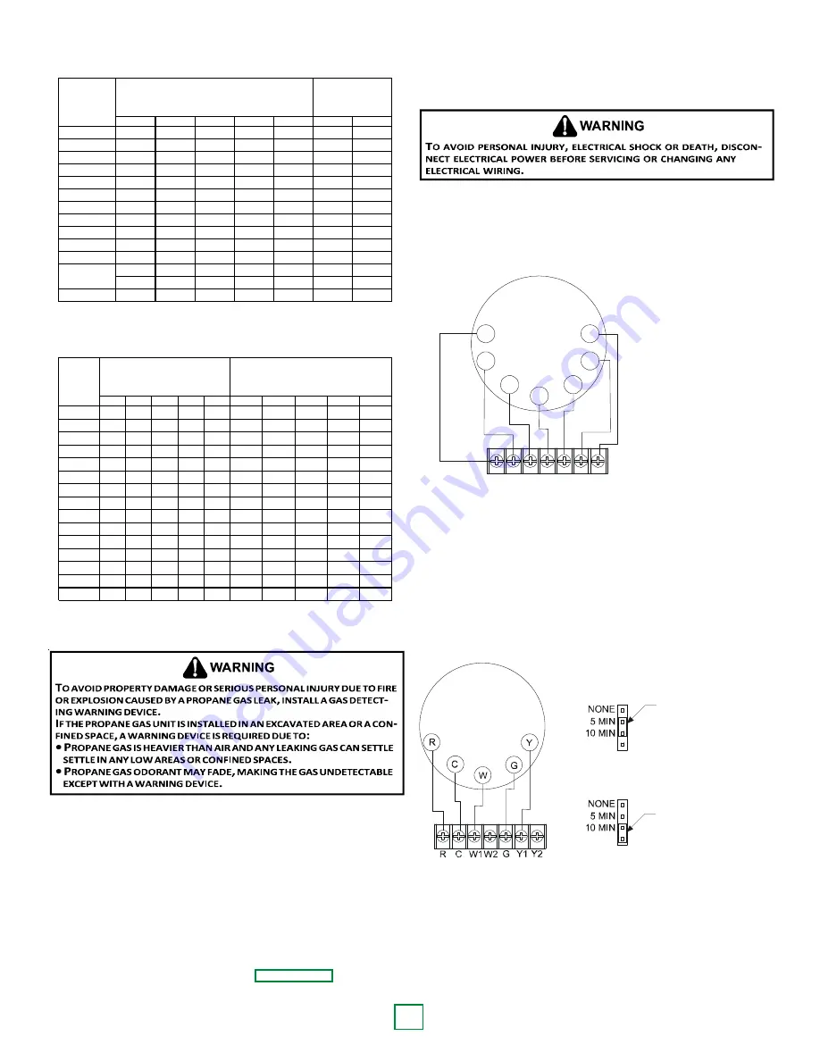
R C W1W2 G Y1 Y2

R

Y2

C

Y1

W1

G

W2

Furnace Integrated

Control Module

Thermostat

Two-Stage Heating

with

Two-Stage Cooling

(

(

Two-Stage Heating with Two-Stage Cooling

Thermostat Diagram

S

INGLE

 S

TAGE

 T

HERMOSTAT

To use a single stage thermostat, move jumper located to the
left of the terminal strip labeled “Stage Delay” from NONE to
“5” or “10” minutes. This selection will cause the control to
run on low stage for the selected time (5 or 10 minutes) then
shift to HIGH STAGE. This option controls both cooling and
heating modes. If the jumper is not moved, only low-stage
cool and low-stage heat will operate.

5 MINUTE DELAY
PERIOD WITH
JUMPER IN THIS
POSITION

10 MINUTE DELAY
PERIOD WITH
JUMPER IN THIS
POSITION

Two-Stage Heating (timed) and Two-Stage Cooling (timed)

with Single Stage Thermostat Diagram

Refer to the unit wiring diagram for electrical connections.
When installed, the unit must be electrically grounded in
accordance with local codes or in the absence of local codes,
with the National Electrical Code, ANSI/NFPA No. 70, and/or
the CSA C22.1 Electrical Code. Ensure low voltage
connections are waterproof.

Sizing Between First and Second Stage Regulator
Maximum Propane Capacities listed are based on 1 PSIG Pressure Drop at 10
PSIG Setting.  Capacities in 1,000 BTU/HR

3/8"

1/2"

5/8"

3/4"

7/8"

1/2"

3/4"

30

309

700

1,303

2,205

3,394

1,843

3,854

40

265

599

1,115

1,887

2,904

1,577

3,298

50

235

531

988

1,672

2,574

1,398

2,923

60

213

481

896

1,515

2,332

1,267

2,649

70

196

446

824

1,394

2,146

1,165

2,437

80

182

412

767

1,297

1,996

1,084

2,267

90

171

386

719

1,217

1,873

1,017

2,127

100

161

365

679

1,149

1,769

961

2,009

150

130

293

546

923

1,421

772

1,613

200

111

251

467

790

1,216

660

1,381

250

90

222

414

700

1,078

585

1,224

300

89

201

378

634

976

530

1,109

350

82

185

345

584

898

488

1,020

400

76

172

321

543

836

454

949

To convert to Capacities at 15 PSIG Settings -- Multiply by 1.130
To convert to Capacities at 5 PSIG Settings -- Multiply by 0.879

PIPE OR

TUBING

LENGTH,

FEET

NOMINAL PIPE SIZE,

SCHEDULE 40

TUBING SIZE, O.D., TYPE L

Sizing Between Single or Second Stage Regulator and Appliance*
Maximum Propane Capacities Listed are Based on 1/2" W.C. Pressure Drop at
11" W.C. Setting.  Capacities in 1,000 BTU/HR

3/8"

1/2"

5/8"

3/4"

7/8"

1/2"

3/4"

1"

1-1/4"

1-1/2"

10

49

110

206

348

539

291

608

1,146

2,353

3,525

20

34

76

141

239

368

200

418

788

1,617

2,423

30

27

61

114

192

296

161

336

632

1,299

1,946

40

23

52

97

164

253

137

284

541

1,111

1,665

50

20

46

86

146

224

122

255

480

985

1,476

60

19

42

78

132

203

110

231

436

892

1,337

80

16

36

67

113

174

94

198

372

764

1,144

100

14

32

59

100

154

84

175

330

677

1,014

125

12

28

52

89

137

74

155

292

600

899

150

11

26

48

80

124

67

141

265

544

815

200

10

22

41

69

106

58

120

227

465

697

250

9

19

36

61

94

51

107

201

412

618

300

8

18

33

55

85

46

97

182

374

560

350

7

16

30

51

78

43

89

167

344

515

400

7

15

28

47

73

40

83

156

320

479

*DATA IN ACCORDANCE WITH NFPA PAMPHLET NO. 54

NOMINAL PIPE SIZE,

SCHEDULE 40

TUBING SIZE, O.D., TYPE L

PIPE OR

TUBING

LENGTH,

FEET

Propane Gas Pipe Sizing

ELECTRICAL WIRING

T

HERMOSTAT

 L

OCATION

Mount the thermostat approximately five feet above the floor,

in an area that has an inside, vibration-free wall  and has

good air circulation.
Movement of air must not be obstructed by furniture, door,

draperies, etc. The thermostat must not be mounted where it
will be affected by drafts, hot or cold water pipes or air ducts in

walls, radiant heat from fireplace, lamps, the sun, television,

etc. Consult the Instruction Sheet packaged with thermostat
for mounting instructions.

NOTE: 

*PG1524, *PG1530, *PG1537, and *PG1549 units have

one stage of mechanical cooling and two stages of heat. All other

units have two stages of heating and two stages of mechanical

Summary of Contents for GPG152407041

Page 1: ...tion Sheet referred to in this manual RECOGNIZE THIS SYMBOL AS A SAFETY PRECAUTION ATTENTION INSTALLING PERSONNEL Prior to installation thoroughly familiarize yourself with this Installation Manual Observe all safety warnings During installation or repair caution is to be observed It is your responsibility to install the product safely and to educate the customer on its safe use These installation...

Page 2: ...ORK 10 FILTERS 11 VENTING 11 INSTALLATION FLUE HOOD EXHAUST 11 INSTALLATION COMBUSTION AIR INTAKE HOOD 11 CONDENSATEDRAIN 11 CONDENSATE DRAIN CONNECTION 11 NORMAL SEQUENCES OF OPERATION 12 HEATING 12 COOLING 12 FAN ONLY 12 STARTUP ADJUSTMENTS AND CHECKS 12 HEATING STARTUP 12 COOLING STARTUP 15 TROUBLESHOOTING 15 IGNITION CONTROL ERROR CODES 15 FAULT RECALL 15 ABNORMAL OPERATION HEATING 16 INTERNAL...

Page 3: ...E PASSAGES QUALIFIED SERVICER ONLY 17 MAIN BURNER FLAME QUALIFIED SERVICER ONLY 18 CLEANING BURNERS 18 ACCESSORIES AND FUNCTIONAL PARTS 18 SHEET METAL ACCESSORIES 18 FUNCTIONAL PARTS 18 GENERAL INFORMATION 18 APPENDIX 19 IGNITION CONTROL DIAGNOSTIC INDICATOR CHART 21 HEATING TIMING CHART 21 COOLING TIMING CHART 21 UNIT DIMENSIONS 22 PG15 41A WIRING DIAGRAM 23 PG15 41B WIRING DIAGRAM 23 MINIMUM CLE...

Page 4: ...FFAIRS GOODMAN MANUFACTURING COMPANY L P 7401 SECURITY WAY HOUSTON TEXAS 77040 713 254 4729 SAFETY INSTRUCTIONS TO THE INSTALLER Before installing this unit please read this manual to familiarize yourself on the specific items which must be adhered to including maximum external static pressure to unit air temperature rise minimum or maximum CFM and motor speed connections TO THE OWNER A warranty c...

Page 5: ...ed by compounds containing chlorine or fluorine Common sources of such compounds include swimming pool chemicals and chlorine bleaches paint stripper adhesives paints varnishes sealers waxes which are not yet dried and solvents used during construction and remodeling Various commercial and industrial processes may also be sources of chlorine fluorine compounds To avoid possible illness or death of...

Page 6: ...54 ANSI Z223 1 and National Standard of Canada CAN CSA B149 Installation Codes The heating and cooling capacities of the unit should be greater than or equal to the design heating and cooling loads of the area to be conditioned The loads should be calculated by an approved method or in accordance with A S H R A E Guide or Manual J Load Calculations published by the Air Conditioning Contractors of ...

Page 7: ...to the Installation Manual provided with the LP kit for conversion from natural gas to propane gas and for altitude adjustments Use HA02 for installations above 2000 PIPING IMPORTANTNOTE To avoid possible unsatisfactory operation or equipment damage due to under firing of equipment do not undersize the natural propane gas piping from the meter tank to the unit When sizing a trunk line include all ...

Page 8: ... procedure The unit is placed in operation by closing the main electrical disconnect switch for the unit PROPANE GAS INSTALLATIONS IMPORTANTNOTE Propane gas conversion kits must be installed to convert units to propane gas Refer to the gas piping section for the correct LP kit for conversion All propane gas equipment must conform to the safety standards of the National Board of Fire Underwriters S...

Page 9: ...649 70 196 446 824 1 394 2 146 1 165 2 437 80 182 412 767 1 297 1 996 1 084 2 267 90 171 386 719 1 217 1 873 1 017 2 127 100 161 365 679 1 149 1 769 961 2 009 150 130 293 546 923 1 421 772 1 613 200 111 251 467 790 1 216 660 1 381 250 90 222 414 700 1 078 585 1 224 300 89 201 378 634 976 530 1 109 350 82 185 345 584 898 488 1 020 400 76 172 321 543 836 454 949 To convert to Capacities at 15 PSIG S...

Page 10: ... through Goodman s Service Parts department DuctCoverInstallation DownDischargeApplications Cut insulation around bottom openings and remove panels from the bottom of the unit saving the screws holding the panels in place NOTE Single phase models require installation of horizontal duct kit 20464501PDGK medium chassis and 20464502PDGK large chassis DUCTWORK Duct systems and register sizes must be p...

Page 11: ... must be a means of filtering all return air All units may be externally filtered Refer to the unit filter size chart in the appendix for filter size information Filters installed external to the unit should be sized in accordance with their manufacturer recommendations A throwaway filter must be sized for a maximum face velocity of 300 feet per minute FilterInstallation IMPORTANTNOTE When install...

Page 12: ...l is for high stage cooling the compressor and outdoor fan are energized at high stage 3 The indoor blower will energize approximately 6 seconds later 4 The unit delivers cooling to the conditioned space until the thermostat is satisfied 5 The compressor and outdoor fan will be de energized when the thermostat opens 6 The indoor blower continues to run at low cool speed for approximately 60 second...

Page 13: ...M Outlet Pressure Boss Open to Atmosphere White Rodgers Model 36G54 connected to Manometer Gas Supply And Manifold Check Gas supply pressure and manifold pressure with the burners operating must be as specified on the rating plate Gas Inlet Pressure Check Gas inlet pressure must be checked and adjusted in accordance to the type of fuel being consumed With Power And Gas Off 1 Connect a water manome...

Page 14: ...w c Gas Manifold Gas Pressure 8 Remove regulator cover screw from the low LO outlet pressure regulator adjust tower and turn screw clockwise to increase pressure or counterclockwise to decrease pressure 9 Energize main M solenoid as well as the HI terminal 10 Remove regulator cover screw from the HI outlet pressure regulator adjust tower and turn screw clockwise to increase pressure or countercloc...

Page 15: ...rol is equipped with a momentary push button switch that can be used to display on the diagnostic LED the last five faults detected by the control The control must be in Standby Mode no thermostat inputs to use the feature Depress the push button switch for approximately 2 seconds NOTE Do not hold for longer than 4 seconds Holding the button for 4 seconds or higher will erase the memory Release th...

Page 16: ... fault is three 3 flashes OPEN THERMAL PROTECTION DEVICE If a limit switch opens the gas valve is immediately de energized the induced draft and air circulating blowers are energized The induced draft and air circulator blowers remain energized until the limit switch re closes The diagnostic LED red code for an open limit is four 4 flashes PRIMARY LIMIT A primary limit will open due to excessive s...

Page 17: ...anable it should be replaced CABINET FINISH MAINTENANCE Use a fine grade automotive wax on the cabinet finish to maintain the finish s original high luster This is especially important in installations with extended periods of direct sunlight CLEAN OUTSIDE COIL QUALIFIED SERVICER ONLY The coil with the outside air flowing over it should be inspected annually and cleaned as frequently as necessary ...

Page 18: ... For further information on the yearly inspection consult the User Manual It is recommended that a qualified servicer inspect and service the unit at least once each year Turn the unit on at the thermostat Wait a few minutes since any dislodged dust will alter the normal flame appearance Flames should be predominantly blue and directed into the tubes They should not be yellow They should extend di...

Page 19: ...19 APPENDIX ...

Page 20: ...es Indoor Outdoor Thermostat Open Cooling Only Devices Not present On All Models 9 Flashes High Pressure Loss of Charge Switch Open Cooling Only Devices Not Present On All Models Amber Light Signal Refer to Abnormal Heating or Cooling Operation Sections of this Manual Off No Flame Present On Normal Flame 1 Flash Low Flame Current 2 Flashes Flame Detected with Gas Valve De energized 90 120 150 180 ...

Page 21: ...UPPLY ENTRANCE CONDENSATE DRAIN CONNECTION 3 4 NPT FEMALE 16 1 8 19 1 8 EVAPORATOR CONTROL PANEL ACCESS PANEL 4 3 4 B 7 15 16 16 B 5 1 2 1 3 8 16 2 3 4 A 18 7 16 FLUE EXHAUST 51 47 BLOWER ACCESS PANEL 22 22 11 11 3 SUPPLY RETURN SUPPLY RETURN 5 3 4 5 1 4 C 20 24 DIMENSION INCHES MEDIUM LARGE A 32 40 B 16 18 C 9 1 2 14 CENTER OF GRAVITY COMBUSTION AIR INTAKE FLUE EXHAUST HOOD UNIT DIMENSIONS ...

Page 22: ...BR PU OR OR OR RD BK BK RD BL PU PU PU PU OR BR WH BL BK PU BL PU YL IGN FS OR LS SOL HI LOW ODF L1 HIGH 6 3 1 2 4 5 1 2 3 4 5 6 7 8 9 NONE 5 MIN 10 MIN 180 150 120 90 Y2 Y1 G W2 W1 C R BLOWER OFF DELAY STAGE DELA Y ECON LO HEAT HI HEAT HI COOL LO COOL FS T1 LOW INDUCER L2 C H M PU BK YL YL H C F RD PU YL RD GR SEE NOTE 3 EM 208 PU YL PU BK N G L BR BR 240 3 TR 2 RD 24V C 1 YL BL 208 230 1 60 POWE...

Page 23: ...LO COOL HI HEAT LO HEAT P2 MVC MVH MVL PSW PSW HLO TH 2 3 5 6 4 1 5 7 9 8 6 3 1 2 L1 L1 HI LO HI SOL GV EM C CC C HI M RS PS LS ALS TR EM VM H F C L2 T2 208 230 1 60 CM L1 R T1 S C SUPPLY VOLTAGE P1 INTEGRATED IGNITION CONTROL CHECK CHECK FOR SHORTS IN FLAME SENSOR WIRING NORMAL FLAME PRESENT DIAGNOSTIC LED AMBER GAS PRESSURE FLAME SENSOR GAS VALVE GAS FLOW CHECK GAS VALVE ON OFF 1 FLASH 2 FLASHES...

Page 24: ...ORE SERVICING ULTIPLE POWER SOURCES MAY BE PRESENT AILURE TO DO SO MAY CAUSE PROPERTY DAMAGE PERSONAL INJURY OR DEATH Wiring is subject to change Always refer to the wiring diagram on the unit for the most up to date wiring PG15 41B WIRING DIAGRAM ...

Page 25: ...ORE SERVICING ULTIPLE POWER SOURCES MAY BE PRESENT AILURE TO DO SO MAY CAUSE PROPERTY DAMAGE PERSONAL INJURY OR DEATH Wiring is subject to change Always refer to the wiring diagram on the unit for the most up to date wiring PG15 41B WIRING DIAGRAM ...

Page 26: ...o more than 36 3 MIN 12 MIN 12 MIN 36 MIN FOR SERVICE 48 MIN MINIMUM CLEARANCES RECOMMENDED FILTER SIZES UNIT 2 Ton 2 1 2 Ton 3 Ton 3 1 2 4 Ton 5 Ton Min Filter Size 1 20 x 20 x 1 1 20 x 25 x 1 1 25 x 25 x1 2 20 x 20 x 1 2 20 x 25 x 1 ...

Page 27: ... 1237 275 1504 381 0 4 895 174 X 1105 255 X 1178 283 1178 283 1451 388 0 5 830 181 X 1045 262 X 1120 291 1120 291 1399 396 0 6 765 189 984 270 X 1061 299 1061 299 1347 404 0 7 699 197 924 278 1002 306 1002 306 1294 412 0 8 634 205 944 314 944 314 1242 420 CFM WATTS RISE CFM WATTS RISE CFM WATTS CFM WATTS CFM WATTS 0 1 1164 180 56 1435 293 61 1477 310 1477 310 1709 407 0 2 1100 188 59 1378 301 63 1...

Page 28: ...IED SERVICER ONLY Your package unit should be inspected by a qualified installer or service agency at least twice every year This check should be performed before the heating and cooling seasons begin This will ensure that adequate combustion air is being drawn and the vent system is working properly Particular attention should be paid to the following items Repair as necessary Check physical supp...

Reviews: