Goodman GPG13 Installation & Operating Instructions Manual Download Page 6

6

T

RANSPORTATION

 D

AMAGE

Check the carton upon arrival for external damage. If damage is
found, a request for inspection by carrier agent should be made in
writing immediately.

Carefully inspect the unit for damage including damage to the
cabinetry.  Any bolts or screws which may have loosened in transit
must be re-tightened.  In the event of damage, the receiver should:

1. Make notation on delivery receipt of any visible damage to

shipment or container.

2. Notify carrier promptly and request an inspection.
3. In case of concealed damage, carrier should be notified

as soon as possible-preferably within 5 days.

4. File the claim with the following supporting documents:

a. Original Bill of Lading, certified copy, or indemnity bond.
b. Original paid freight bill or indemnity in lieu thereof.
c. Original invoice or certified copy thereof, showing trade

and other discounts or reductions.

d. Copy of the inspection report issued by carrier

representative at the time damage is reported to the
carrier. The carrier is responsible for making prompt
inspection of damage and for a thorough investigation of
each claim. The distributor or manufacturer will not accept
claims from dealers for transportation damage.

NOTE:

 When inspecting the unit for transportation damage, remove

all packaging materials. Recycle or dispose  of the packaging ma-
terial according to local codes.

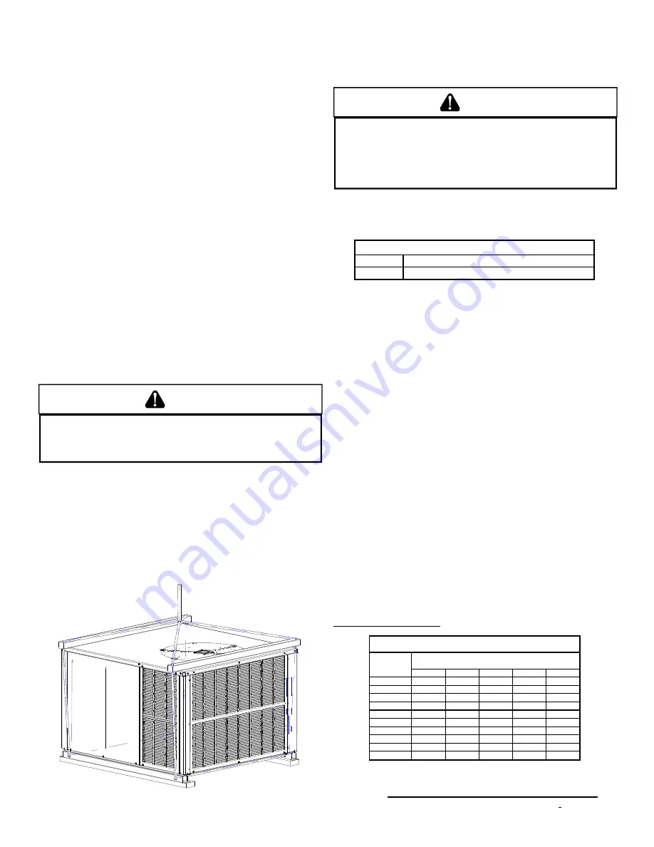
RIGGING DETAILS

WARNING

T

O PREVENT PROPERTY DAMAGE, THE UNIT SHOULD REMAIN IN AN UPRIGHT

POSITION DURING ALL RIGGING AND MOVING OPERATIONS. 

T

O FACILITATE

LIFTING AND MOVING WHEN A CRANE IS USED, PLACE THE UNIT IN AN

ADEQUATE CABLE  SLING.

Important:

 If using bottom discharge with roof curb, ductwork should

be attached to the curb prior to installing the unit. Ductwork dimen-
sions are shown in roof curb installation instructions.

Refer to the Roof Curb Installation Instructions for proper curb in-
stallation. Curbing must be installed in compliance with the National
Roofing Contractors Association Manual.

Lower unit carefully onto roof mounting curb. While rigging unit,
center of gravity will cause condenser end to be lower than supply
air end.

Rigging

GAS PIPING

IMPORTANT NOTE: 

This unit is factory set to operate on natural

gas at the altitudes shown on the rating plate.

WARNING

T

O AVOID PROPERTY DAMAGE, PERSONAL INJURY OR DEATH WHEN EITHER

USING PROPANE GAS ALONE OR AT HIGHER ALTITUDES, OBTAIN AND INSTALL

THE PROPER CONVERSION KIT(S). 

F

AILURE TO DO SO CAN RESULT IN 

UNSATISFACTORY OPERATION AND/OR EQUIPMENT DAMAGE. 

H

IGH ALTITUDE

KITS ARE FOR 

U

.

S

. INSTALLATIONS ONLY AND ARE NOT APPROVED FOR USE

IN 

C

ANADA.

The rating plate is stamped with the model number, type of gas and
gas input rating. Make sure the unit is equipped to operate on the
type of gas available.  Conversion to LP gas is permitted with the
use of the factory authorized conversion kit LPT-00A.

Inlet Gas Pressure

Natural

Min. 5.0" W.C., Max. 10.0" W.C.

Propane

Min. 11.0" W.C., Max. 13.0" W.C.

Inlet Gas Pressure Must Not Exceed the Maximum Value Shown in Table
Above.

The minimum supply pressure should not vary from that shown in
the table above because this could prevent the unit from having
dependable ignition. In addition, gas input to the burners must not
exceed the rated input shown on the rating plate. Overfiring of the
unit could result in premature heat exchanger failure.

H

IGH

 A

LTITUDE

 D

ERATE

  (U.S. I

NSTALLATIONS

 O

NLY

)

IMPORTANT NOTE: 

The gas/electric units naturally derate with al-

titude. Do not attempt to increase the firing rate by changing ori-
fices or increasing the manifold pressure. This can cause poor com-
bustion and equipment failure.  At all altitudes, the manifold pres-
sure must be within 0.3 inches W.C. of that listed on the nameplate
for the fuel used. At all altitudes and with either fuel, the air tempera-
ture rise must be within the range listed on the unit nameplate.
Refer to the Installation Manual  provided with the LP kit for conver-
sion from natural gas to propane gas and for altitude adjustments.

P

IPING

IMPORTANT NOTE: 

To avoid possible unsatisfactory operation or

equipment damage due to under firing of equipment, do not under-
size the natural/propane gas piping from the meter/tank to the unit.
When sizing a trunk line, include all appliances on that line that
could be operated simultaneously.
The rating plate is stamped with the model number, type of gas
and gas input rating. Make sure the unit is equipped to operate on
the type of gas available.  The gas line installation must comply
with local codes, or in the absence of local codes, with the latest
edition of the National Fuel Gas Code NFPA 54/ANSI Z223.1.

Natural Gas Connection

Length of 

Pipe in Feet

1/2

3/4

1

1 1/4

1 1/2

10

132

278

520

1050

1600

20

92

190

350

730

1100

30

73

152

285

590

980

40

63

130

245

500

760

50

56

115

215

440

670

60

50

105

195

400

610

70

46

96

180

370

560

80

43

90

170

350

530

90

40

84

160

320

490

100

38

79

150

305

460

Pressure = .50 PSIG or less and Pressure Drop of 0.3" W.C. (Based 

on 0.60 Specific Gravity Gas)

Natural Gas Capacity of Pipe

in Cubic Feet of Gas Per Hour (CFH)

Nominal Black  Pipe Size (inches)

B T U H  F urnace Inp ut

H eatin g  V alu e  of  G as  (B T U /C ub ic F o ot)

C F H   =

Summary of Contents for GPG13

Page 1: ...Requirements Embodied in The American National Standard National Standard of Canada Shown Below ANSI Z21 47 CSA 2 3 Central Furnaces RECOGNIZE THIS SYMBOL AS A SAFETY PRECAUTION ATTENTION INSTALLING...

Page 2: ...11 HEATING 11 COOLING 11 FAN ONLY 12 Startup Adjustments and Checks 12 HEATING STARTUP 12 COOLING STARTUP 15 Troubleshooting 15 IGNITION CONTROL ERROR CODES 15 ABNORMAL OPERATION HEATING 16 ABNORMAL O...

Page 3: ...L TO SHUT OFF TURN OFF THE MANUAL GAS SHUTOFF VALVE EXTERNAL TO THE FURNACE BEFORE TURNING OFF THE ELECTRICAL SUPPLY WARNING THIS PRODUCT CONTAINS OR PRODUCES A CHEMICAL OR CHEMICALS WHICH MAY CAUSE S...

Page 4: ...the outdoor air i e combustion air for the unit will be frequently contaminated by compounds containing chlorine or fluorine Common sources of such compounds include swimming pool chemicals and chlor...

Page 5: ...TION ELECTRIC SHOCK OR CARBON MONOXIDE THIS UNIT MUST BE PROPERLY INSTALLED REPAIRED OPERATED AND MAINTAINED This unit is approved for outdoor installation ONLY To assure that your unit operates safel...

Page 6: ...TION AND OR EQUIPMENT DAMAGE HIGH ALTITUDE KITS ARE FOR U S INSTALLATIONS ONLY AND ARE NOT APPROVED FOR USE IN CANADA The rating plate is stamped with the model number type of gas and gas input rating...

Page 7: ...E A MATCH OR OPEN FLAME TO TEST FOR LEAKS NEVER EXCEED SPECIFIED PRESSURES FOR TESTING HIGHER PRESSURE MAY DAMAGE GAS VALVE AND CAUSE OVERFIRING WHICH MAY RESULT IN PREMATURE HEAT EXCHANGE FAILURE THI...

Page 8: ...acturers and propane gas suppliers Since propane gas will quickly dissolve white lead or most standard commercial compounds special pipe dope must be used Shellac base compounds resistant to the actio...

Page 9: ...SI Z21 20 AUTOMATIC IGNITION SYSTEM L2 L2 L2 L2 ECON 120 135 150 SPEED UP LOW VOLTAGE CONNECTOR Y Y2 Low Voltage Wiring PG1360 1A Only Refer to the unit wiring diagram for electrical connections When...

Page 10: ...onal Board of Fire Underwriters for the Installation of Air Conditioning Warm Air Heating and Ventilating Systems Pamphlets No 90A and 90B The supply duct from the unit through a wall may be installed...

Page 11: ...lower will deenergize This allows any additional heat in the heat exchanger to be transferred to the conditioned space PG13 48 60 1A ONLY HEAT FAN OFF delay is fixed at 180 seconds Airflow level is 50...

Page 12: ...lout protection device is located on the burner bracket The reason for elevated temperatures at the control should be determined and repaired prior to resetting this manual reset control WARNING TO AV...

Page 13: ...gas being delivered to the unit 3 INPUT GAS HTG VALUE x 3600 SEC PER CUBIC FOOT Example Natural gas with a heating value of 1000 BTU per cubic foot and 34 seconds per cubic foot as determined by Step...

Page 14: ...utward from the burner without curling floating or lifting off Temperature Rise Check Check the temperature rise through the unit by placing thermometers in supply and return air registers as close to...

Page 15: ...does not operate Compressor Protection Devices The compressor includes components which are designed to protect the compressor against abnormal operating conditions WARNING TO PREVENT PERSONAL INJURY...

Page 16: ...and carefully clean with steel wool Check wiring Check wiring for opens shorts and miswiring Important If you have to frequently reset your gas electric package unit it means that a problem exists th...

Page 17: ...bris CONDENSER EVAPORATOR AND INDUCED DRAFT MOTORS Bearings on the air circulating blower motor condenser motor and the combustion fan motor are permanently lubricated No additional oiling is required...

Page 18: ...rical power and gas supply CAUTION LABEL ALL WIRES PRIOR TO DISCONNECTION WHEN SERVICING CONTROLS WIRING ERRORS CAN CAUSE IMPROPER AND DANGEROUS OPERATION CAUTION ALWAYS VERIFY PROPER OPERATION AFTER...

Page 19: ...Seconds 0 7 30 0 60 Circulator Blower Outdoor Fan and Compressor Thermostat ON OFF ON OFF ON OFF Legend PG10 12 24 60 PG1324 42 PG1348 60 100 50 Light Signal Refer to Abnormal Heating or Cooling Opera...

Page 20: ...SUPPLY ENTRANCE CONDENSATE DRAIN CONNECTION 3 4 NPT FEMALE 16 1 8 19 1 8 EVAPORATOR CONTROL PANEL ACCESS PANEL 4 3 4 B 7 15 16 16 B 5 1 2 1 3 8 16 2 3 4 A 18 7 16 FLUE EXHAUST 51 47 BLOWER ACCESS PAN...

Page 21: ...H OPTIONAL CONNECTED AT L1 L2 NOTE 4 B BL Y R FS R O R H C F Y BR CAP1 BL B PU 4 SPEED MOTOR ALS Y Y PS PU W G G W R BL Y Y PU R C Y Y2 Y1 Y BL 6 5 2 3 G 4 1 Y PU PL RS MV GAS VALVE MV GV PU W R BL GV...

Page 22: ...ER BEFORE SERVICING OR INSTALLING THIS UNIT MULTIPLE POWER SOURCES MAY BE PRESENT FAILURE TO DO SO MAY CAUSE PROPERTY DAMAGE PERSONAL INJURY OR DEATH B4312003 REV B Wiring is subject to change Always...

Page 23: ...TC OT1 O T2 BR CM PU B Y COMP B B S C R CH OPTIONAL BL C LS R R BL BL PU BL R PU R R G G Y W PU Y1 Y 208 230 1 60 POWER SUPPLY B NOTE 2 B B BL BL BL BL B PU L1 B R CC L2 T1 T2 R B Y GRD R Y R Y2 CH O...

Page 24: ...ENSER MOTOR CC CONTACTOR CH CRANKCASE HEATER FS FLAME SENSOR COMPONENT LEGEND CAP CAPACITOR L2 L2 MARKED TERMINAL LINE VOLTAGE LOW VOLTAGE UNMARKED TERMINAL WIRING WIRE SPLICE Y Y C Y2 Y2 1 REPLACEMEN...

Page 25: ...PU B Y COMP B B S C R CH OPTIONAL BL C LS R R BL BL PU BL R PU R R G G Y Y Y2 W PU Y1 Y 208 230 1 60 POWER SUPPLY B NOTE 2 B B BL BL BL BL B PU L1 B R CC L2 T1 T2 R B Y GRD R Y1 PU PU BL BL BL PU Y Y...

Page 26: ...NSER MOTOR CC CONTACTOR CH CRANKCASE HEATER FS FLAME SENSOR COMPONENT LEGEND CAP CAPACITOR L2 L2 MARKED TERMINAL LINE VOLTAGE LOW VOLTAGE UNMARKED TERMINAL WIRING WIRE SPLICE SOL SOLENOID 2 STAGE nd Y...

Page 27: ...U PU PU BL BR 1 4 3 2 5 6 F C 240 24V 1 C 2 208 3 NOTE 4 GAS VALVE NOTE 5 ALT HONEYWELL W R GAS VALVE PLF Y1 Y2 Y C R W G CH OPTIONAL CONNECTED AT L1 L2 NOTE 3 NOTE 4 NOTE 2 208 230 3 60 CH OPTIONAL P...

Page 28: ...ALS LS 8 6 3 RS PLF 6 5 2 3 C 1 4 GV FALSE FLAME SENSED OUTPUT DELAY OPEN LIMIT SWITCH COMPRESSOR ANTI CYCLE TIMER MAIN LIMIT OPEN STICKING GAS VALVE BAD SWITCH 3 MIN COMP WITHOUT INDUCER ON PRESSURE...

Page 29: ...ECON 120 150 11 8 12 9 7 10 4 2 5 6 3 1 DI L1 FS HEAT UNUSED L2 GND POWER SUPPLY 208 230 3 60 CH OPTIONAL CONNECTED AT L1 L2 NOTE 3 Y1 Y2 CH OPTIONAL NOTE 5 PLF T1 T2 T3 T4 T5 NOTE 4 NO TE2 SEE NOTE 6...

Page 30: ...CITOR WITH ECONOMIZER OPTION WH GR RD PU BL BL YL RD GR WH NO ECONOMIZER WH W W 0140G00087 Y C W R G Y C R G PU Y1 BL YL Y2 C GR RD G R THERMOSTAT FIELD WIRING 2 STAGE COOLING NOTE 3 TR NOTE NOTE 7 NO...

Page 31: ...IONAL 460 3 60 SEE NOTE 6 BK BK PU RD BK YL RD GND RD BK BK RD CH OPTIONAL CONNECTED AT L1 L2 NOTE 2 SEE NOTE 3 SEE NOTE 5 TO THERMOSTAT VM GAS VALVE IGN FS MV ALT HONEYWELL GAS VALVE MV W R GV 5 4 1...

Page 32: ...TYPE OF INSULATION AS ORIGINAL USE COPPER CONDUCTOR ONLY 0140G00088 4 ACCESSORY ECONOMIZER PLUG ON SELECT MODELS ADJACENT SPEED REPLACE THE BLACK MOTOR LEAD AT IBR 3 WITH RED 3 460V UNITS ARE SINGLE...

Page 33: ...WH WH RD BK PU BL W R GAS VALVE GAS VALVE ALT HONEYWELL TO THERMOSTAT R C G Y W COOL P1 ECON 11 8 12 9 7 10 4 2 5 6 3 1 DI L1 FS HEAT UNUSED L2 GND POWER SUPPLY 460 3 60 CH OPTIONAL CONNECTED AT L1 L...

Page 34: ...PTION WH GR RD PU BL BL YL RD GR WH NO ECONOMIZER WH W W 0140G00089 Y C W R G Y C R G PU Y1 BL YL Y2 C GR RD G R THERMOSTAT FIELD WIRING 2 STAGE COOLING NOTE 2 TR NOTE NOTE 6 NOTE 6 4 SEE NOTE 7 EM R...

Page 35: ...135 ECON 120 150 11 8 12 9 7 10 4 2 5 6 3 1 DI L1 FS HEAT UNUSED L2 GND POWER SUPPLY 208 230 1 60 CH OPTIONAL CONNECTED AT L1 L2 NOTE 3 Y1 Y2 CH OPTIONAL NOTE 5 PLF T1 T2 T3 T4 T5 NOTE 4 N OTE2 SEE N...

Page 36: ...ZER OPTION WH GR RD PU BL BL YL RD GR WH NO ECONOMIZER WH W W 0140G00267 Y C W R G Y C R G PU Y1 BL YL Y2 C GR RD G R THERMOSTAT FIELD WIRING 2 STAGE COOLING NOTE 3 TR NOTE NOTE 7 NOTE 7 5 NOTE 2 EM R...

Page 37: ...Ton 2 1 2 Ton 3 Ton 3 1 2 4 Ton 5 Ton Min Filter Size 1 20 x 20 x 1 1 20 x 25 x 1 1 25 x 25 x1 2 20 x 20 x 1 2 20 x 25 x 1 MINIMUM CLEARANCES NOTE Roof overhang should be no more than 36 3 MIN 12 MIN...

Page 38: ...38 THIS PAGE LEFT BLANK INTENTIONALLY...

Page 39: ...39 THIS PAGE LEFT BLANK INTENTIONALLY...

Page 40: ...significantly reduce the most frequent causes of product failure They are simple to service and forgiving to operate We use quality materials and components Finally every unit is run tested before it...

Reviews: