SS-GM9S80-U
www.goodmanmfg.com
3
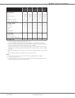
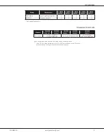
GM9S80-U Product Specifications
GM9S80
0403AU*
GM9S80
0603AU*
GM9S80
0604BU*
GM9S80
0804BU*
GM9S80
0805CU*
Heating Capacity
Input
40,000
60,000
60,000
80,000
80,000
Natural Gas Output
32,000
48,000
48,000
64,000
64,000
AFUE ¹
80
80
80
80
80
Available AC @ 0.5” ESP
3
3
4
4
5
Temperature Rise Range (°F)
25-55
20-50
20-50
35-65
35-65
Circulator Blower
Size (D x W)
10" x 6"
10" x 6"
10" x 8"
10" x 8"
10" x 10"
Horsepower
0.5
0.5
0.75
0.75
1
Speed
9
9
9
9
9
Vent Diameter ²
4"
4"
4"
4"
4"
No. of Burners
2
3
3
4
4
Electrical Data
Min. Circuit Ampacity ³
8.7
8.7
12.45
12.45
12.7
Max. Overcurrent Device (amps) ⁴
15
15
15
15
15
Ship Weight (lbs)
86
90
100
108
116
¹ DOE AFUE based upon Isolated Combustion System (ICS)
² Vent and combustion air diameters may vary depending upon vent length. Refer to the latest
editions of the National Fuel Gas Code NFPA 54/ANSI Z223.1 (in the USA) and the Canada National
Standard of Canada, CAN/CSA B149.1 and CAN/CSA B142.2 (in Canada).
³ Minimum Circuit Ampacity = (1.25 x Circulator Blower Amps) + ID Blower amps. Wire size should
be determined in accordance with National Electrical Codes. Extensive wire runs will require larger
wire sizes.
⁴ Maximum Overcurrent Protection Device refers to maximum recommended fuse or circuit breaker
size.
May use fuses or HACR-type circuit breakers of the same size as noted.
Notes
•
All furnaces are manufactured for use on 115 VAC, 60 Hz, single-phase electrical supply.
•
Gas Service Connection ½” FPT
•
Important: Size fuses and wires properly and make electrical connections in accordance with the
National Electrical Code and/or all existing local codes.


