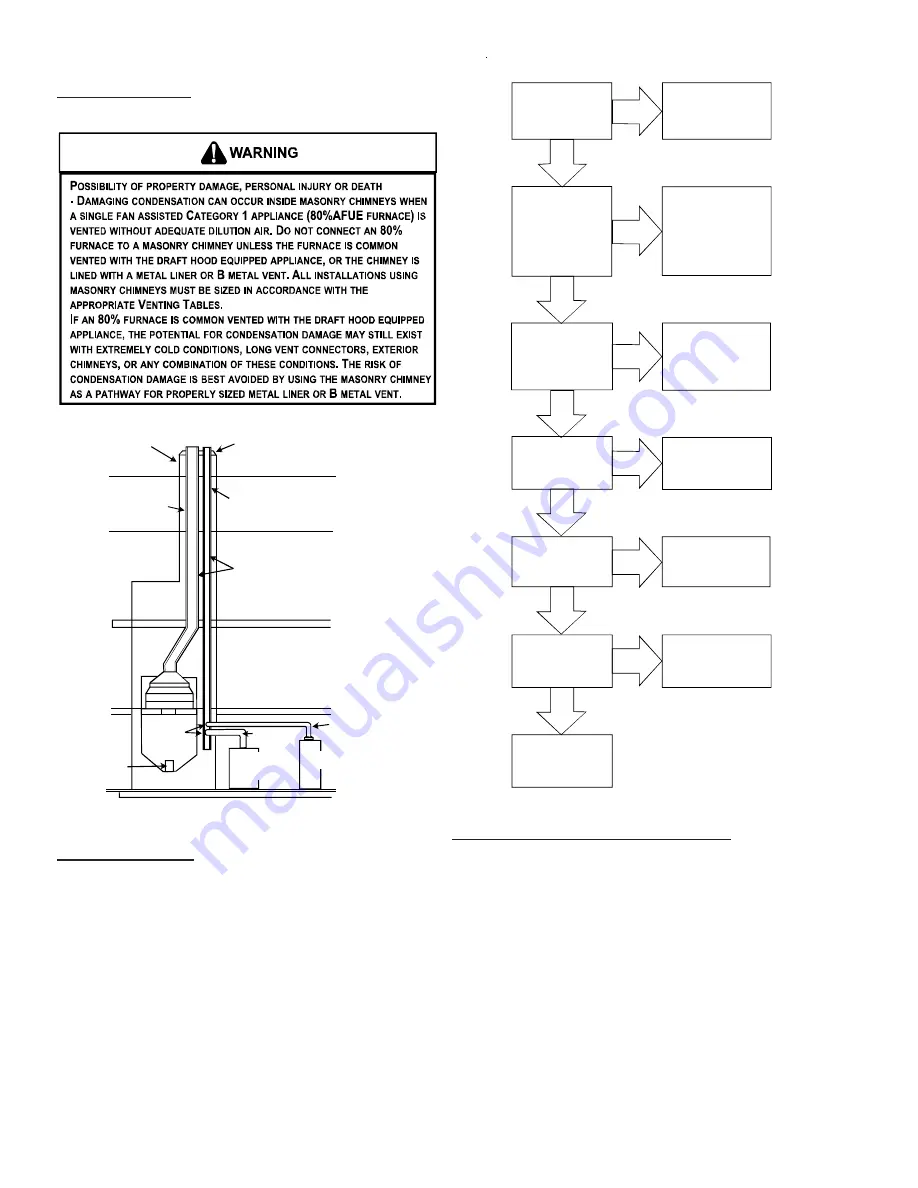
Goodman ACS series Service Instructions Manual Download Page 36

PRODUCT DESIGN

36

Masonry Chimneys

Wash

Crown

Clay Tile Size: 8" x 8" x12"

(Each x 24" Length)

Clay Tile Size Generally
12" x 12" (24" Length)

1/2" to 1" Air Space

Second Floor

First Floor

Attic Floor

Roof Line

Throat

Damper

Breech

Clean Out

Fan Assisted
Forced Air
Furnace

Natural Draft
Water Heater

Water Heater
Vent Connector

Basement Floor

F.A.F. Vent
Connector

Typical Multiple Flue Clay Tile Chimney

Checklist Summary

This checklist serves as a summary of the items to be
checked before venting an 80% furnace into a masonry
chimney. In addition, we recommend that a qualified ser-
viceman use this checklist to perform a yearly inspection of
the furnace venting system.
This checklist is only a summary. For detailed information
on each of the procedures mentioned, see the paragraph
referenced with each item.
This inspection is based upon a draft topical report, "Ma-
sonry Chimney Inspection and Relining", issued by the Gas
Research Institute. While not yet finalized, we believe this
report represents the best information on this subject which
is currently available.

Proper Chimney

Termination?

(Check 1)

Line, terminate with

listed vent cap

(Fix 1)

No

Yes

Chimney channel

free of solid and

liquid fuel

appliances?

(Check 2)

Change venting

arrangements 

(Fix 2)

No

Yes

Crown in good

condition

(Check 3)

Rebuild crown

(Fix 3)

and/or Reline

(Fix 4)

Yes

No

Yes

No

No

Reline
(Fix 4)

Reline
(Fix 4)

Cleanout free of

debris?

(Check 4)

Liner in good

condition?

(Check 5)

Yes

Yes

No

Reline
(Fix 4)

Dilution air

available?

(Check 6)

Complete the

installation.

(Check 7)

Check 1  - Proper chimney termination.

A masonry chimney used as a vent for gas fired equipment
must extend at least three feet above the highest point where
it passes through the roof. It must extend at least two feet
higher than any portion of a building within a horizontal dis-
tance of 10 feet. In addition, the chimney must terminate at
least 3 feet above any forced air inlet located within 10 feet.
The chimney must extend at least five feet above the high-
est connected equipment draft hood outlet or flue collar.
If the chimney does not meet these termination requirements,
but all other requirements in the checklist can be met, it
may be possible for a mason to extend the chimney. If this
will not be practical, see Fix 1.

Summary of Contents for ACS series

Page 1: ...ice Instructions This manual is to be used by qualified professionally trained HVAC technicians only Goodman does not assume any responsibility for property damage or personal injury due to improper s...

Page 2: ...NE OR OTHER FLAMMABLE LIQUIDS OR VAPORS IN THE VICINITY OF THIS APPLIANCE TABLE OF CONTENTS IMPORTANTINFORMATION 2 3 PRODUCTIDENTIFICATION 4 14 OPERATINGINSTRUCTIONS 20 22 ACCESSORIES 23 27 PRODUCT DE...

Page 3: ...ed area Carbon monoxide emissions can be re circulated throughout the structure if the furnace or air handler is operating in any mode CO can cause serious illness including permanent brain damage or...

Page 4: ...D 24 1 2 M Upflow Horizontal D Dedicated Downflow C Downflow Horizontal H High Air Flow Product Type Furnace Type Airflow Capability 0 5 ESP 045 45 000 Btuh 070 70 000 Btuh 090 90 000 Btuh 115 115 00...

Page 5: ...ignition control and Million Air stainless steel tubular heat exchanger Chassis sizes are now 17 5 21 wide AMV8 BA AMV8 BA AMV8 BB Amana Brand 80 Variable Speed Gas Furnace 2 stage heat gas furnace 3...

Page 6: ...izontal Left or Right Induced Draft new grey painted cabinet and front panels PSC motor standardized blower decks and a 120V silicon nitride igniter Left or right gas pipe entry The furnaces also feat...

Page 7: ...peed 2 stage Gas Furnace Downflow Horizontal Left and Right 40 tall 2 stage Induced Draft new two tone grey painted cabinet and front panels standardized blower decks and a Surestart Silicon Nitride I...

Page 8: ...40 tall 2 stage Induced Draft furnace redesign changes that include new two tone grey painted cabinet and front panels standardized blower decks and a Surestart Silicon Nitride Igniter Left or right g...

Page 9: ...adding a side drain port hole The side port drain tube is only used when placing the furnace in the horizontal left application DMS9 P1256701F P1256706F Amana Distinctions Brand 90 Gas Furnace Upflow...

Page 10: ...1 Gas Furnace Upflow Horizontal Left or Right 40 tall Induced Draft new grey painted cabinet and front panels PSC motor standardized blower decks and a Carbide Mini Igniter Left or right gas pipe entr...

Page 11: ...nace in the horizontal left application GMH95 GMH95 AA GMH95 AB GMH95 AC Goodman Brand 95 Gas Furnace Upflow Horizontal Left or Right 40 tall Induced Draft new two tone grey painted cabinet and front...

Page 12: ...Carbon filters optional remove odors Dual indicator lights show unit operation at a glance Electronic proving switch cycles the air cleaner On Off with the system fan Durable powder coat paint finish...

Page 13: ...ce models AMH8 AMS8 ADS8 DMS8 DDS8 DHS8 GDS8 GMH8 GMS8 GDS8 GHS8 for higher altitudes This kit is required when installing these furnaces above their maximum rated altitude This kit contains 43 49 55...

Page 14: ...Amana Brand s 90 single stage and two stage gas fired furnace product installed on LP gas listed in this manual The kit monitors gas line pressure with a pressure switch and disables the unit s gas va...

Page 15: ...5 X X AMH81155CNA X 5 X X AMH81405DNA X 5 X X AMS80453ANA X X X X AMS80703ANA X X X X AMS80704BNA X X X X AMS80903BNA X X X X AMS80904BNA X X X X AMS80905CNA X X X X AMS81155CNA X X X X AMS81405DNA X...

Page 16: ...se 21 Propane Gas Conversion Kit GDS80453ANA X X X X X GDS80703ANA X X X X X GDS80904BNA X X X X X GDS81155CNA X X X X X GDH80453AXA X 5 X X X X GDH80703AXA X 5 X X X X GDH80904BXA X 5 X X X X GDH8115...

Page 17: ...4 X X ACS90703BXA X X X X X X 4 1 2 4 X X ACS90704CXA X X X X X X 4 1 2 4 X X ACS90904CXA X X X X X X X 4 1 2 4 X X ACS90905DXA X X X X X X X 4 1 2 4 X X ACS91155DXA X X X X X X 4 1 2 4 X X AMH950453B...

Page 18: ...ternal Filter Retention Kit Downflow GCH90453BXA X X X X X X 5 2 3 4 2 X X GCH90703BXA X X X X X X 5 2 3 4 2 X X GCH90704CXA X X X X X 5 2 3 4 2 X X GCH90904CXA X X X X X 5 2 3 4 2 X X GCH90905CXA X X...

Page 19: ...s equipped with an ignition device which automatically lights the burner Do not try to light the burner by hand B BEFORE OPERATING smell all around the appliance area for gas Be sure to smell next to...

Page 20: ...equipped with an ignition device which automatically lights the burner Do not try to light the burner by hand B BEFORE OPERATING smell all around the appliance area for gas Be sure to smell next to t...

Page 21: ...If the gas control switch or knob D Do not use this appliance if any part has been under water Immediately call a qualified service technician to inspect the appliance and to replace any part of the c...

Page 22: ...l eau Si cela se produit demandez immediatement a un reparateur qualifie d inspecter l appareil et de remplacer toute piece du systeme de controle et toute commande de gaz ayant ete dans l eau 0140F00...

Page 23: ...L FILTER RACK KIT Used on Models 90 Upflow Model Furnaces BLOWER DECK SCREWS SLOTS IN FILTER CLEAR SCREWS ON UNIT FRONT OF UNIT RETURN AIR CUTOUT AREA LOWER EDGE SCREW FILTER RACK ASSEMBLY FACE FILTER...

Page 24: ...ER RAIL SCREW SIDE PANEL BASE FILTER ANGLES 2 FILTER ANGLE SCREW FILTER ANGLE SCREW RF000180 RF000181 RF000180 Quantity Part Description 20 10690301 Filter Angle 20 20242801 Filter Rail 10 20178501 Fi...

Page 25: ...nstallation The DCVK 20 2 or the DCVK 30 3 is a new concentric vent kit approved with furnaces listed in this manual This concentric vent kit allows for vertical or horizontal vent termina tion The il...

Page 26: ...s This kit is NOT intended for use with single pipe indirect vent installations The vent kit must terminate outside the structure and may be installed with the intake and exhaust pipes located side by...

Page 27: ...tion of Concentric Vent Assembly Must Be Adequately Secured and Supported Sanitary Tee Connection for Fresh Air Intake Pipe to Furnace Connection for Vent Flue Pipe From Furnace 12 Minimum Above Roof...

Page 28: ...plication This product is designed for use as a residential home gas furnace It is not designed or certified for use in mobile home trailer or recreational vehicle applications This furnace can be use...

Page 29: ...instructions to determine if the piping system from furnace to termination can be accomplished within the guidelines given NOTE The length of flue and or combustion air piping can be a limiting factor...

Page 30: ...y a concrete pad Never install the furnace on the ground or allow it to be exposed to water The length of rod will depend on the application and the clearances necessary TILT OUTWARD TO ALLOW FOR DOOR...

Page 31: ...in single stage thermostat position DIP switch position 3 ON Delay Period 10 minutes DIP switch position 3 OFF Delay Period 5 minutes T W O S I N G L E TSTAT ON NOTE The AMH GCH GDH GMH and GME hybri...

Page 32: ...roper circulation of combustion ventilation and dilution air 9 3 1 4 Where used a draft hood or a barometric draft regulator shall be installed in the same room or enclosure as the appliance served so...

Page 33: ...put rating of all equipment in the enclosure Inlet Air Ventilation louvers for unheated crawl space Alternate air inlet Ventilation louvers each end of attic Figure A 9 3 3 1 1 a All Combustion Air Fr...

Page 34: ...size of openings for com bustion ventilation and dilution air shall be based on the net free area of each opening Where the free area through a design of louver or grille or screen is known it shall b...

Page 35: ...ome conditions larger vents than those shown above may be required or allowed When an existing furnace is removed from a venting system serving other appliances the venting system may be too large to...

Page 36: ...ubject which is currently available Proper Chimney Termination Check 1 Line terminate with listed vent cap Fix 1 No Yes Chimney channel free of solid and liquid fuel appliances Check 2 Change venting...

Page 37: ...the upper edge of the cleanout cover is at least 12 inches below the lower edge of the lowest chimney inlet opening A chimney without a cleanout could become partially blocked by debris If no cleanout...

Page 38: ...a CAN CGA B149 1 and CAN CGA B149 2 latest editions and amendments then the clay tile liner can probably be used as a vent for the gas appliances However the installer must keep in mind the following...

Page 39: ...the National Standard of Canada CAN CGA B149 1 and CAN CGA B149 2 latest editions and amend ments To install the liner read and follow the liner manufacturer s instructions and your local codes Exces...

Page 40: ...ositions Refer to Vent Flue Pipe and Combustion Air Pipe section in this manual or the installation instructions for details concerning the con version to the alternate vent flue and combustion air co...

Page 41: ...s the responsibility of the installer to follow the manufac turers recommendations and to verify that all vent flue pip ing and connectors are compatible with furnace flue prod ucts Additionally it is...

Page 42: ...of the terminations shown in this manual or in unheated areas must be insu lated with 1 2 thick closed cell foam such as Armaflex or Insultube Inspect piping for leaks prior to installing insula tion...

Page 43: ...tions a minimum of one 90 elbow must be installed on the combustion air intake coupling to guard against inadvertent blockage Combustion Air Pipe 90 Furnaces Only Direct Vent Installations On upflow u...

Page 44: ...t Flue Location Alternate Combustion Air Intake Location 90 Fur naces Only NOTE Alternate combustion fresh air inlet location on the right hand panel side of 90 furance models was discontinued since N...

Page 45: ...tion must be included when deter mining the number of elbows in the piping system 4 3 diameter pipe can be used in place of 2 diameter pipe 5 Increased Clearance Configurations using 2 45 deg Long Swe...

Page 46: ...an outside wall Vertical vent flue pipe termination should be as shown in the following figures Refer to Vent Flue Pipe and Combus tion Air Pipe Termination Locations section in this manual or the ins...

Page 47: ...ms of a direct vent dual pipe installation The number of elbows tabulated represents the number of elbows and or tees in each Vent Flue Com bustion Air Intake pipe Elbows and or tees used in the termi...

Page 48: ...Vent Flue Air Intake Termination 045_3 090_4 070_3 070_4 090_5 1 Elbows and or tees used in terminations must be included when determining quantity of allowable elbows in the system 2 Number of elbows...

Page 49: ...ge to piping connections a coupling should be installed on either side of the wall and solvent cemented to a pipe connecting the two couplings The pipe length should be the wall thickness plus the dep...

Page 50: ...such as above planters patios or adjacent to windows where steam may cause fogging 4 The vent termination shall be located at least 4 horizontally from any electric meter gas meter regulator and any...

Page 51: ...for Canada minimum clearance above highest anticipated snow level Maximum of 24 above roof Combustion Air Roof Boot Flashing Field Supplied Support Field Supplied 45 Elbow Field Supplied Combustion A...

Page 52: ...ases A Exhaust Combustion Air 12 Min Grade 18 for Canada or Snow Level Dimension A is touching or 2 maximum separation FIGURE 8 1 Maximum TYP A Vent Combustion Air Vent Exhaust Dimension A is touching...

Page 53: ...cing Couplings if required Seal all holes through wall with sealant 3 Pipe Condensate Drain Lines and Drain Trap 90 Furnaces Only A condensing gas furnace achieves its high level of effi ciency by ext...

Page 54: ...PANEL GROMMET HOLES HOSE B HOSE A RUBBER ELBOW RED HOSE CLAMP RED HOSE CLAMP 90 Furnace Upright Standard Drain Hose Connections Right Side LEFT SIDE PANEL FRONT COVER DRAIN PORT HOSE A SIDE PANEL GROM...

Page 55: ...ressure switch hose must be connected to the down side to guard against blocked drain conditions The hose must be cut to appropriate length to minimize sagging LEFT SIDE PANEL FRONT COVER DRAIN PORT S...

Page 56: ...fferent pressure switch may be required at high altitude regardless of the BTU ft3 content of the fuel used Refer to the product Specification Sheet or Technical Manual for a tabular listing of approp...

Page 57: ...n is in stalled the union must be downstream of the manual shutoff valve between the shutoff valve and the fur nace 8 Tighten all joints securely 9 Connect the furnace to the building piping by one of...

Page 58: ...ALVE GROUND JOINT PIPE UNION BURNERS GROMMET IN STANDARD GAS LINE HOLE COUNTERFLOW MANUAL SHUT OFF VALVE UPSTREAM FROM GROUND JOINT PIPE UNION ALTERNATE GAS LINE LOCATION PLUG IN ALTERNATE GAS LINE HO...

Page 59: ...isfactory operation propane gas pressure must be 11 inch WC at the furnace manifold with all gas appliances in operation Maintaining proper gas pressure depends on three main factors 1 Vaporization ra...

Page 60: ...the contractor must consider proper tank sizing safety efficiency ground char acteristics and aesthetics For a residential customer the size may range from 100 1 000 gallons depending on house hold us...

Page 61: ...N 80 Furnace Junction Box Relocation STANDARD JUNCTION BOX LOCATION ALTERNATE JUNCTION BOX LOCATION 90 Furnace Junction Box Relocation NOTE Wire routing must not interfere with circulator blower opera...

Page 62: ...to allow use with most cooling equip ment Consult the wiring diagram located in the Technical Manual or on the blower door for further details of 115 Volt and 24 Volt wiring THERMOSTAT WIRING 80 90 S...

Page 63: ...mostat Application 80 and 90 Variable Speed Two Stage Furnaces A single stage thermostat with only one heating stage can be used to control this furnace The application of a single stage thermostat do...

Page 64: ...stat Y On Two Stage Integrated Control Module Circulator blower will operate on selected High Stage Cooling speed tap 5 second ON delay and 45 second OFF delay Low Stage Connection For Two Stage Cooli...

Page 65: ...UT FOR DEHUM lo cated adjacent to the DEHUM screw terminal NOTE W14 imprinted on the circuit board is the CUT FOR DEHUM location Once the jumper wire is cut the dehumidify function is enabled during a...

Page 66: ...hipped with heating speed set at B and cooling speed set at D Use the following procedure to select the heating and cooling speed needed for your unit Use the GREEN CFM LED adjacent to the integrated...

Page 67: ...Verify profile selection by counting the green CFM LED blinks and timing each step of the ramping profile Profile A provides only an OFF delay of one 1 minute at 100 of the cooling demand airflow OFF...

Page 68: ...IMINGS 80 90 Furnaces NOTE Items in this section refer to the air circulator blower fan NOTtotheinduceddraftblower Theinduceddraftblower timing sequence is not adjustable The circulator blower fan tim...

Page 69: ...X25X1 350 21 16x25x1 400 24 1 2 20X25X1 500 SIDE RETURN BOTTOM RETURN Refer to Minimum Filter Area tables to determine filter area requirement NOTE Filterscanalsobeinstalledelsewhere in the duct syste...

Page 70: ...m return ductwork connec tion Upflow furnaces with air delivery of 1800 CFM or higher Use two side returns or one side return and one bottom return connection Guide dimples locate the side and bottom...

Page 71: ...r replacement is relatively simple by merely removing the grille rather than going into the attic or crawl space ADDITIONAL FILTERING ACCESSORIES Internal Filter Retention Kit These kits can be used o...

Page 72: ...de energized following a fifteen 15 second post purge Humidifier terminals are de energized 11 Circulator blower is de energized following a selectable heat off delay period 90 120 150 or 180 seconds...

Page 73: ...onal sequence in sequence is as fol lows R and W thermostat contacts close initiating a call for heat Integrated control module performs safety circuit checks Induced draft blower is energized for 15...

Page 74: ...or fan and compressor are de energized Circulator blower is de energized following a fixed forty five second cool off delay period Electronic air cleaner terminals are de energized Furnace awaits the...

Page 75: ...the control will immediately switch the induced draft blower and gas valve to their low stage settings The circulator blower will remain on high heat ing speed for thirty 30 seconds before switching...

Page 76: ...essor are energized to their ap propriate speed 4 Circulator blower is energized on the appropriate cool speed at the level and time determined by the selected ramping profile Electronic air cleaner t...

Page 77: ...120 150 or 180 seconds Electronic air cleaner terminals are de energized The adjustable delay off timing allows the installer to cus tomize the comfort level COOLING MODE The normal operational seque...

Page 78: ...30 seconds to ramp up to full speed Electronic air cleaner terminals are energized with circulator blower 10 Furnace is now operating on the specified stage called for by the two stage thermostat 11 F...

Page 79: ...ower runs integrated control module monitors safety circuits continuously 5 R and G thermostat contacts open completing the call for fan 6 Circulator blower is de energized Electronic air cleaner term...

Page 80: ...oblem is two short flashes followed by a longer pause The probable cause is either a faulty pressure switch or wiring 4 Pressure Switch Stuck Open If after the induced draft blower is energized the pr...

Page 81: ...ort flashes followed by a longer pause The prob able cause is either a faulty pressure switch or wiring 4 Pressure Switch Stuck Open If after the induced draft blower is energized the pressure switch...

Page 82: ...control senses the pressure switch is closed when the induced draft blower is off it waits until the fault is corrected The diagnostic light code for this problem is two short flashes followed by a l...

Page 83: ...gs If the two stage thermostat changes the call from high heat to low heat the control will immediately switch the induced draft blower and gas valve to their low stage settings The circulator blower...

Page 84: ...ed chloride free soap and water solution an electronic combustible gas detector or other approved method Verify that all required kits pro pane gas high altitude etc have been appropriately in stalled...

Page 85: ...is problem is two short flashes followed by a longer pause The prob able cause is either a faulty pressure switch or wiring 4 Pressure Switch Stuck Open If after the induced draft blower is energized...

Page 86: ...improper circulator blower speed or failed circulator blower Pressure switch circuit is closed Induced draft blower is not operating Replace induced draft blower pressure switch Repair short Furnace f...

Page 87: ...nit ground Review wiring diagram to correct polarity Reverse wires connected to 24 volt side of transformer Verify proper ground Correct if necessary Check and correct wiring if necessary Turn power O...

Page 88: ...power OFF prior to repair Igniter is fragile handle with care Sand flame sensor with emery cloth See Vent Flue Pipe section for piping details Furnace fails to operate Integrated control module diagno...

Page 89: ...rated control module diagnostic LED is flashing SEVEN 7 flashes Flame sense microamp signal is low Sand flame sensor is coated oxidized Inspect for proper sensor alignment Check inlet air piping for b...

Page 90: ...cessary Inspect flue for blockage proper length elbows and termination Correct pressure switch setpoint or contact motion Tighten or correct wiring connection Pressure switch hose blocked pinched or c...

Page 91: ...ows and termination Compare current gas pressure to rating plate info Adjust as needed Turn power OFF prior to repair Turn power OFF prior to repair Sand flame sensor with emery clot See Vent Flue Pip...

Page 92: ...wired to the furnace accordingly CHECKING FOR PHASING PRIMARY TO SECONDARY OF UNMARKED TRANSFORMERS If meter reads approximately 96 volts the primary to secondary are in phase if reads approximately...

Page 93: ...oper furnace operation Remember that dirty filters are the most common cause of inadequate heating or cooling performance Maintenance Improper filter maintenance is the most common cause of inadequate...

Page 94: ...to reduce the chances of repeated fouling FLAME SENSOR QUALIFIED SERVICER ONLY Under some conditions the fuel or air supply can create a nearly invisible coating on the flame sensor This coating acts...

Page 95: ...of the unit adjust the gas valve pressure regulator or resize orifices ALWAYS CONNECT A MONOMETER TO THE OUTLET TAP AT THE GAS VALVE BEFORE ADJUSTING THE PRESSURE REGULATOR IN NO CASE SHOULD THE FINA...

Page 96: ...160 400 20 45 90 180 360 900 46 78 157 391 21 43 86 171 343 857 47 19 38 76 153 383 22 41 82 164 327 818 48 75 150 375 23 39 78 157 313 783 49 147 367 24 37 75 150 300 750 50 18 36 72 144 360 25 36 72...

Page 97: ...Ignition Control Test Control S 313 Gas Valve or Gas Supply Shut Off Turn Valves to On Position S 317 Faulty Induced Draft Blower Test Induced Draft Motor S 303 Faulty Blower Motor PSC ECM Test Blower...

Page 98: ...TURE RISE 113 S 300 CHECKING PRIMARY LIMIT CONTROL 114 S 301 CHECKING AUXILIARY LIMIT CONTROL 115 S 302 CHECKING FLAME ROLLOUT CONTROL 117 S 303 TEST INDUCED DRAFT MOTOR 118 S 304 CHECKING GAS VALVE 1...

Page 99: ...eck continuity of any suspected open wires 3 If any wires must be replaced replace with AWM 105 C 2 64 thick insulation of the same gauge or its equivalent CHECKING THERMOSTAT WIRING AND ANTICIPATOR S...

Page 100: ...PRESENT FAILURE TO DO SO MAY CAUSE PROPERTY DAMAGE PERSONAL INJURY OR DEATH 1 Remove blower compartment door to gain access to the thermostat low voltage wires located at the furnace inte grated cont...

Page 101: ...k S 16A CHECKING AIR CIRCULATOR BLOWER MOTOR PSC ECM DISCONNECT ALL POWER BEFORE SERVICING WARNING 1 Remove blower compartment door to gain access to the circulator blower motor and integrated ignitio...

Page 102: ...form leads the current AC waveform In other words the inductor reduces line current which extends the life of the 3 4 and 1 horsepower motors The furnaces requiring an in ductor are shown in the foll...

Page 103: ...t cooling speed and R to G to W will cause the fan to come on at heating speed If motor does not respond as noted ICM control unit is bad and should be replaced Replacing ICM Control Module Use the fo...

Page 104: ...otor to fail Is there any evidence of water damage to the failed control Corrosion on the inside or outside of the casting If yes do a moisture check 9 Re install the blower motor assembly into the fu...

Page 105: ...ment check ICM 2 motors only Turn power OFF prior to repair Wait 5 minutes after disconnecting power before opening motor Handle electronic motor control with care Motor oscillates up down while being...

Page 106: ...nels etc Check for air whistling thru seams in ducts cabinets or panels Check for cabinet duct deformation Turn power OFF prior to repair Hunts or puffs at high CFM speed High static creating high blo...

Page 107: ...rom the ECM motor Set volt meter to read AC volts Place your voltage meter on Pin 1 Common and Pin 2 W1 you should be reading 13 AC volts Next check between Pin 1 Common and Pin 12 R you should read 2...

Page 108: ...r will come on If you DO NOT have these read ings you may have a 16 pin wire harness or integrated con trol board problem Make sure you have high voltage at the 5 pin connector go ing to the motor as...

Page 109: ...ay have a 16 pin wire harness or integrated con trol board problem Make sure you have high voltage at the 5 pin connector go ing to the motor as discussed earlier We highly recommend using the GE TECM...

Page 110: ...Next check between Pin 1 Com mon adn Pin 6 Y1 you should read 24 AC volts You MUST have all of these low voltage readings before the ECM motor will come on If you DO NOT have these read ings you may h...

Page 111: ...f these low voltage readings before the ECM motor will come on If you DO NOT have these readings you may have a 16 pin wire harness or integrated control board problem Make sure you have high voltage...

Page 112: ...ll of these low voltage readings before the ECM motor will come on If you DO NOT have these read ings you may have a 16 pin wire harness or integrated con trol board problem Make sure you have high vo...

Page 113: ...RN AIR Checking Static Pressure 80 Furnace Shown 90 Similar S 201 CHECKING TEMPERATURE RISE The more air CFM being delivered through a given fur nace the less the rise will be so the less air CFM bein...

Page 114: ...mary Limit Control Location 90 Upflow Furnace Shown Counterflow Similar The following drawing illustrates the style of limit switches used on the 90 furnaces ENCLOSED DISK FRONT VIEW SIDE VIEW Primary...

Page 115: ...the voltage to the gas valve causing it to close The auxiliary limit is located on the front side of the blower housing near the center on all 80 single stage furnaces as shown in the following illus...

Page 116: ...nterflow installations It may also open if the power sup ply is interrupted while the furnace is firing The auxiliary limit control is suitable for both horizontal right and horizontal left installati...

Page 117: ...lor coded labels have been affixed to the back of these controls Refer to the Rollout Limit Charts in furnace Technical Manual for temperature set tings and color codes The circuit between the ignitio...

Page 118: ...ance Main 95 ohms Redundant 98 ohms 2nd Stage 180 ohms 2 Allow at least 20 tolerance for temperature and meter variation Most of the time coils will fail as open circuit If not as above replace the en...

Page 119: ...ECT ELECTRICAL POWER AND SHUT OFF GAS SUPPLY 1 After turning off gas to furnace at the manual gas shutoff valve external to the furnace remove burner compart ment door to gain access to the gas valve...

Page 120: ...ace and check for leaks If leaks are found repair and then reinstall burner compartment door 8 Turn on electrical power and verify proper unit operation Gas Manifold Pressure Measurement and Adjust me...

Page 121: ...ING OR INSTALLING 1 After turning off gas to furnace at the manual gas shutoff valve external to the furnace remove burner compart ment door to gain access to the gas valve 2 Connect a calibrated wate...

Page 122: ...ALLING 11 Disconnect manometer after turning off gas at manual shutoff valve Reinstall gas valve outlet pressure tap plug before turning on gas to furnace 12 Turn on gas to furnace and check for leaks...

Page 123: ...g with inadequate venting caused by a restricted or blocked vent pipe on the 80 and 90 furnaces Also on the 90 furnaces there is a pressure control that will prevent the combustion cycle from occuring...

Page 124: ...und or high resis tance neutral line will significantly shorten the life of the Sillicon Nitride SiNi igniter used in Amana brand 80 and 90 furnaces This section discusses various integrated ignition...

Page 125: ...tral at the ignition control No voltage check the door switch connections and wire harness for continuity 2 Check for 24 volts from W1 to C terminal on the ignition control No voltage Check transforme...

Page 126: ...oltage re place ignition control 4 If voltage is present in Steps 1 through 3 and the in duced draft blower is operating check for 120 volts to the ignitor during the preheat cycle Measure voltage bet...

Page 127: ...n this service manual Goodman and Amana brand 80 and 90 Two Stage AMH8 GME8 GMH8 AMH95 GMH95 GCH9 NOTE The models above use White Rodgers 50M56 289 ignition control board 1 Check for 120 volts from Li...

Page 128: ...80 Upflow Model Shown Counterflow Similar 3 16 1 16 DISTANCE OF IGNITOR TO BURNER DISTANCE OF SENSOR TO BURNER 23 64 1 64 FLAME SENSOR IGNITOR BURNERS Models with Integrated Ignition Control Flame Se...

Page 129: ...P2 4 K1 OT NO Y P2 9 CALL FOR 2ND STAGE COMPRESSOR Y2 1 0K G FURN P2 1 C OT C C SECOND STAGE COMPRESSOR OUTPUT G CALL FOR EMERGENCY HEAT W1 FURN W2 HP F1 3A OT NC 24VAC 2ND STAGE COMPRESSOR DEMAND OUT...

Page 130: ...ATH FURNACE TWINING KIT FTK03A This wiring diagram is for reference only Not all wiring is as shown above Refer to the appropriate wiring diagram for the unit being serviced For use only with 80 or 90...

Page 131: ...AILURE TO DO SO MAY CAUSE PROPERTY DAMAGE PERSONAL INJURY OR DEATH DE HUMIDISTAT DEHUM1 This wiring diagram is for reference only Not all wiring is as shown above Refer to the appropriate wiring diagr...

Reviews: