background image

94

93

TELEPHONE DESCRIPTION

TELEPHONE DESCRIPTION

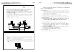
escription of the T-940 Plus telephone.

D

a.
b.

c.

d.
e.

f.

g.
h.

i.

Telephone handset.
Speaker grille.
Microphone hole.
Subjection hole.
Telephone cord connectors.
Function push buttons.
On-Off light indicator.
Call reception volume control.
Hook switch.

a

d

c

e

i

h

e

b

f

g

The telephone has a three positions switch placed on the bottom
     part of the telephone (closest to the telephone cord connector)
     that allows to control the call reception level volume.

unction push buttons.

F

On-Off push button.
     After any telephone reset, and during the next 45 seconds,
     all the telephone functions will be disabled, with the exception
     of call reception.

This push button allows to make an intercom call when the handset
     is not on the craddle. This function is described on page 104.

If the handset is on the craddle sends a panic call to the porter's
     exchanges that have enabled the reception of this type of call.
     If not, allows to call to the master porter's exchange.
     During call reception and communication progresses allows
     the lock release activation.

a.

b.

c.

a

b

c

erminal connector description.

T

positive, ground.
audio, digital communication.
intercom.
auxiliary calling device output.
door bell push button input.

+ ,   :
A , D :
INT :
SA :
HZ- :

A D

+ _

SA

INT

HZ-

TELEPHONE INSTALLATION

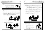
ix the telephone.

F

It will be necessary to open the telephone for wiring and
     fixing purposes. To open the telephone insert a plain
      screwdriver into the slots and rotate it as shown.

Avoid to place the telephone near to
     heating sources, in dusty locations or
     smoky environments.
The telephone can be fixed using an
     electrical embedding box or directly
     on the wall, as shown on the picture.
     If the telephone will be installed directly
     over the wall, drill two holes of Ø6mm.
     on the specified positions, using 6mm.
     wallplugs and Ø3,5 x 25mm. screws.

Pass the installation wires through the corresponding hole and
     connect them as shown on the installation diagrams.
Close the telephone as shown on the picture. Once the telephone
     is closed, connect the handset using the telephone cord and
     put it on the craddle.

Summary of Contents for Stadio Plus

Page 1: ...o a cualquier modificación sin previo aviso Golmar se réserve le droit de toute modification sans préavis Golmar reserves the right to make any modifications without prior notice golmar golmar es www golmar es T500ML rev 0205 manual de instalación version français page 36 english version page 72 ...

Page 2: ... antena En instalaciones de hasta 100m puede utilizar el cable Golmar RAP 5130 que incluye todos los conductores necesarios para la instalación O O O O O O w w w w w w w Equipos microprocesados con instalación simplificada bus sin hilos de llamada wPortero electrónico con instalación de 4 hilos comunes wVideoportero con instalación de 3 hilos comunes más cable coaxial wVideoportero con instalación...

Page 3: ... 125 140 56 Compacto CE615 125 220 56 Módulos Modelo An Al P 2 CE620 125 257 56 3 CE630 125 mm 374 mm 56 mm reparación de la entrada de cables P Romper el tabique para la entrada de cables por la parte inferior de la caja En caso de placas con más de una caja romper los tabiques laterales para cablear los módulos y unir las cajas mediante los túneles pasacables UC 4 DESCRIPCIÓN DE LA PLACA 3 escri...

Page 4: ...to microprocesado EL500 Cy del decodificador EL516 El circuito EL500 se coloca en la parte superior de la caja de empotrar Para ello introducir el circuito en las pestañas superiores 1 de la caja y de empotrar Encajarlo en las pestañas inferiores 2 realizando una fuerte presión sobre el circuito impreso Para colocar el decodificador EL516 centrar el agujero de la parte superior de la tapa del deco...

Page 5: ...e empotrar 8 INSTALACIÓN DE LA PLACA 7 INSTALACIÓN DE LA PLACA Conectar el módulo de sonido al circuito microprocesador EL500 mediante el cable plano suministrado Para un buen acabado de la instalación pasar los cables a través del hueco dispuesto en el separador de módulos más cercano Es recomendable utilizar 2 cable con secciones entre 0 1 y 0 25mm MUY IMPORTANTE unir el común de pulsadores de l...

Page 6: ...circuito EL500 38 68 98 23 53 83 113 9 9 39 69 99 24 54 84 114 10 10 40 70 100 25 55 85 115 11 11 41 71 101 26 56 86 116 12 12 42 72 102 27 57 87 117 13 13 43 73 103 28 58 88 118 14 14 44 74 104 29 59 89 119 15 15 45 75 105 30 60 90 120 ableado de los pulsadores C P8 P7 P6 CN2 del EL500 P5 P4 P3 P2 P1 CP B El conector CN2 del circuito microprocesador EL500 dispone de 8 bornes P1 a P8 para la conex...

Page 7: ...egleta de conexión El puente JP1 carga la instalación con una resistencia de comunicaciones Para un correcto funcionamiento activar esta resistencia sólo en la placa más cercana al montante de instalación o en la placa general si existe Valor de fábrica activada El puente JP2 selecciona el tipo de cableado para la señal de video cable coaxial RG 59 o RG 11 o par trenzado La opción de par trenzado ...

Page 8: ...MPORTANTE el abrepuertas debe ser de 12V corriente contínua Si usted dispone de un abrepuertas de corriente alterna utilice un relé R 3 y un transformador TF 104 tal y como se muestra en la página 24 IMPORTANTE IMPORTANTE M 4 x 8 f3 5 x 25 DIN 7972 DIN 963 justes finales A ableado de las lamparitas de iluminación C Después de colocar las etiquetas identificativas cablear las lamparitas de todos lo...

Page 9: ... técnico WARNING High voltage Don t open cover Handle only by technical service PISO Floor Door Stair PLATEA Plus 0000000000 Nº serie escripción de la etiqueta identificativa D Para facilitar la reparación sustitución o ampliación de monitores existentes en una instalación complete los datos de la etiqueta identificativa MASTER monitor principal SLAVE monitor secundario INTER monitor secundario co...

Page 10: ...idor salida activación 2ª cámara salida activación dispositivo auxiliar señal de vídeo balanceada a través de par trenzado Vin Malla Vout A D HZ INT SA CTO 2C A1 Vp Mp ódulo EL562 para instalaciones de videoportero M con par trenzado Localizar el conector CN4 ubicado en la parte posterior del monitor Retirar el puente del conector e insertar el módulo EL562 NOTA en este tipo de instalaciones el ci...

Page 11: ...a indicar que el equipo está listo para la programación la placa emitirá unos tonos y aparecerá la imagen en el monitor pudiendo soltar el pulsador de abrepuertas Para establecer comunicación de audio con la placa descolgar el auricular Presionar el pulsador de la placa que se desea que llame a este monitor En dicho instante la placa emitirá unos tonos y parpadeará el indicador luminoso del monito...

Page 12: ... recibir este tipo de llamada Con el auricular descolgado permite realizar una llamada normal a la central principal Durante los procesos de recepción de llamada o o comunicación activa el abrepuertas a b c a b c escripción de los bornes de conexión D positivo negativo comunicación audio digital intercomunicación salida sonería auxiliar entrada pulsador timbre de puerta A D INT SA HZ A D _ SA INT ...

Page 13: ...de abrepuertas y sin soltarlo encienda el teléfono Para indicar que el equipo está listo para la programación la placa emitirá unos tonos y el indicador luminoso del teléfono parpadeará pudiendo soltar el pulsador de abrepuertas Para establecer comunicación de audio con la placa descolgar el auricular Presionar el pulsador de la placa que se desea que llame a este teléfono En dicho instante la pla...

Page 14: ...omo muestra el esquema En el caso de más de dos placas conecte las restantes igual que la segunda Colocar este alimentador lo más cerca posible del primer distribuidor 1 00mm 2 50mm 0 25mm 0 25mm RG 59 RG 59 Borne TABLA DE SECCIONES 50m Secciones hasta 150m A A A D in out V V V V in out in out CV CV CV CV D Malla Vin Ain Aout Vin Vout Vout CN1 CV CV D Malla Vin Ain Aout Vin Vout Vout CN1 SW1 SW1 J...

Page 15: ...lo EL560 y que los monitores utilicen el módulo EL562 IMPORTANTE Colocar este alimentador lo más cerca posible del primer distribuidor 1 00mm 2 50mm 0 25mm 0 25mm CAT 5 CAT 5 Borne TABLA DE SECCIONES 50m Secciones hasta 150m A A A D in out V V V M in out p d p d CV CV FA Plus C SEC PRI Red Placa secundaria Placa principal CV CV D Malla Vin Ain Aout Vin Vout Vout CN1 CV CV D Malla Vin Ain Aout Vin ...

Page 16: ...a placa conecte la segunda tal y como muestra el esquema En el caso de más de dos placas conecte las restantes igual que la segunda Colocar este alimentador lo más cerca posible del primer teléfono 1 00mm 2 50mm 0 25mm 0 25mm Borne TABLA DE SECCIONES 50m Secciones hasta 150m A A A D in out CV CV A A _ _ D D T 940 Plus T 940 Plus A _ D T 940 Plus A _ D T 940 Plus FA Plus C SEC PRI Red Placa secunda...

Page 17: ...elevisor através del canal auxiliar Quitar el puente de resistencia de final de línea de 75W ubicado en el conector CN4 de la parte posterior del monitor Conectar el cable coaxial a los terminales 17 malla y 20 vivo del euroconector ntercomunicación entre dos puntos Ide la misma vivienda El monitor Shiner Plus y el teléfono T 940 Plus incorporan de serie la intercomunicación entre dos puntos de la...

Page 18: ...ntes terminales de la instalación nunca dañará a los equipos conectados a excepción de un cortocircuito entre los terminales CTO y del monitor o del distribuidor O No funciona nada w Comprobar que la tensión de salida del alimentador entre los bornes y es de 17 5 a 18 5Vc c Si no es así desconecte el alimentador de la instalación y vuelva a medir la tensión Si ahora es correcta es que hay un cruce...

Page 19: ...35 Stadio Plus manuel d installation Portiers Audio et Portiers Vidéo Système digitale T500ML rev 0205 ...

Page 20: ...tez de serrer de façon excessive les vis du connecteur de l alimentation O Lors de l installation ou de toutes interventions sur le système veiller à couper l alimentation électrique O Avant la mise sous tension vérifier les connexions entre la plaque de rue le moniteur et poste d appel et l alimentation Lorsque le système est mis en marche pour la première fois ou après une intervention le systèm...

Page 21: ...RIPTION DE LA PLAQUE DE RUE escription du portier D Modules grille 1xxx 2xxx Têtes 600 Modules poussoirs 3xxx Boîtiers d encastrement CE 6xx Groupes phoniques EL530 EL531 EL540 pour systèmes portier vidéo avec caméra n b pour systèmes portier vidéo avec caméra coleur pour systèmes portier audio pour tous les systèmes pour systèmes avec plus de 8 poussoirs Module d extension EL516 Circuit microproc...

Page 22: ...e suivant assurez vous que les encoches du séparateur restent à l intérieur du portier Fixer le deuxième module en vissant les axes filetés Répéter l opération pour les portiers composés de plus de 1 module le nombre maximum de modules est 3 Insérer le traverse de fixation supérieure marquée ARRIBA dans le dernier module et fixer cette dernière au moyen des vis fournies Passer les câbles à travers...

Page 23: ...vrir la fenêtre du porte étiquette Placer l étiquette et refermer Connecter le groupe phonique au circuit microprocesseur EL500 au moyen du câble plat fourni ise en place des étiquettes d identification des poussoirs d appel M INSTALLATION DE LA PLAQUE DE RUE INSTALLATION DE LA PLAQUE DE RUE ixation de la plaque de rue sur le boîtier d encastrement F Déterminer le sens d ouverture de la plaque de ...

Page 24: ...le 1er poussoir ou la borne P du 1er circuit EL516 Vers le 2ème poussoir ou la borne P du 2ème circuit EL516 Vers le 3ème poussoir ou la borne P du 3ème circuit EL516 Vers le 4ème poussoir ou la borne P du 4ème circuit EL516 Vers le 5ème poussoir ou la borne P du 5ème circuit EL516 Vers le 6ème poussoir ou la borne P du 6ème circuit EL516 Vers le 7ème poussoir ou la borne P du 7ème circuit EL516 V...

Page 25: ...l Pour les installations avec plusieures plaques de rue cette fonction ne peut être activée que sur une seule plaque Pour les installations avec plaque générale une plaque de chaque bâtiment peut avoir cette fonction Suite escription des micro interrupteurs de configuration Ddu circuit microprocesseur EL500 Les micro interrupteurs de configuration SW1 sont situés sur la partie centrale du circuit ...

Page 26: ...égler le volume audio du système pour cela procéder à l aide d un tournevis comme indiqué sur le dessin La télécaméra dispose d un mécanisme d orientation horizontale et verticale Si l orientation n est pas correcte corriger sa position Dans le cas dune illumination insufissante on peut activer une illumination extérieure au moyen d un relais R 3 connecté entre les bornes H et L2 du groupe phoniqu...

Page 27: ...cté à un dispositif auxiliaire CODIGO code du poussoir d appel voir page 46 ESCALERA code du bâtiment voir page 48 Poussoir allumage extinction ON OFF du moniteur Après chaque réinitialisation du moniteur et durant les 45 secondes suivantes aucune opération ne pourra être réalisée à l exception de la réception d appel Avec le combiné raccroché activation de la seconde caméra Avec le combiné décroc...

Page 28: ...iangle comme indiqué sur le dessin odule EL562 pour installation de système vidéo M avec paire torsadée Vin Vout Malla Shield Malla Shield A HZ INT SA CTO 2C A1 VP MP D REF RCPL PLUS LOTE CODE 11758882 Colocar la parte superior de la regleta a 1 60m del suelo Place the top part of the monitor connector at 1 60m from the floor 50mm 50mm Presionar para abrir Press to open Les bornes de connexion et ...

Page 29: ... plus d une plaque de rue effectuer cette opération uniquement sur le plaque principal Eteindre le moniteur à programmer Une fois le moniteur éteint presser le bouton de commande de la gâche électrique Tout en maintenant le bouton de commande de gâche appuyé allumer le moniteur La plaque de rue émet un signal sonore et l image apparaît sur le moniteur indiquant que ce dernier peut être programmé R...

Page 30: ...ppel panique aux centrales de conciergerie configurées pour recevoir ce type d appel Avec le combiné décroché permet de réaliser un appel normal vers la centrale principale Durant le processus de réception d appel ou une communication permet de commander la gâche électrique a b c escription du bornier de connexion D positif négatif communication audio digital intercommunication sortie sonnerie aux...

Page 31: ...on Pour les systèmes comportant plus d une plaque de rue effectuer cette opération uniquement sur le plaque principal La plaque de rue émet un signal sonore et l indicateur lumineux du poste clignote indiquant que ce dernier peut être programmé Relacher le bouton de commande de gâche et décrocher le combiné pour établir communication Presser le poussoir de la plaque correspondant au poste devant r...

Page 32: ... pour un même bâtiment Si l installation dispose d une seule plaque ne pas tenir compte des autres plaques Si l installation comporte deux plaques connecter la seconde comme indiqué sur le schéma Lors d installations avec plus de deux plaques connecter les autres plaques de la même façon que la seconde 1 00mm 2 50mm 0 25mm 0 25mm RG 59 RG 59 Borne TABLE DES SECTIONS 50m Sections jusqu à 150m A A A...

Page 33: ...ule plaque ne pas tenir compte des autres plaques Si l installation comporte deux plaques connecter la seconde comme indiqué sur le schéma Lors d installations avec plus de deux plaques connecter les autres plaques de la même façon que la seconde IMPORTANT Ce type d installation requiert l utilisation d un module EL560 dans chaque plaque et l utilisation d un module EL562 dans chaque moniteur IMPO...

Page 34: ... possible du premier poste ortier audio P 1 00mm 2 50mm 0 25mm 0 25mm Borne TABLE DES SECTIONS 50m Sections jusqu à 150m A A A D in out CV CV Le schéma d installation montre la connexion d un système portier audio avec une ou plusieurs portes d accès pour un même bâtiment Si l installation dispose d une seule plaque ne pas tenir compte des autres plaques Si l installation comporte deux plaques con...

Page 35: ...gnétoscope ntercommunication entre deux postes Ide la même habitation Les moniteurs Platea Plus et les postes T 940 Plus incluent de série l intercommunication entre deux postes de la même habitation Pour pouvoir utiliser cette fonction il est nécessaire que Un des postes soit configuré comme principal et l autre comme secondaire avec la fonction d intercommunication comme indiqué en pages 56 et 5...

Page 36: ...différentes bornes ou fils n endommagera jamais les équipements connectés à l exception d un court circuit entre les bornes CTO et du moniteur ou du distributeur O Rien ne fonctionne w Vérifier la tension de sortie entre les bornes et de l alimentation Celle ci doit être comprise entre 17 5 et 18 5Vc a Si ce n est pas le cas déconnecter l alimentation de l installation et mesurer la tension Si cel...

Page 37: ...71 Stadio Plus Instructions manual Audio and Video door entry system digital installation T500ML rev 0205 ...

Page 38: ...f minutes or until the handset is replaced Once the communication has finished the system will be freed O To open the door press the door release push button during call or communication progresses with one press the door release operates during 3 seconds During the lock release activation an acoustic tone will be heard on the door panel confirming the lock release is activated O The monitor and t...

Page 39: ...f the door panel should be placed at 1 65m height roughly The hole dimensions will depend on the number of door panel modules The door panel has been designed to be placed under most of the environmental conditions However it s recommended to take additional cautions like rainproof covers To obtain a good quality picture on video door entry systems avoid direct incidence from light sources reparin...

Page 40: ...N marked in the lower module and fix it by screwing the module shafts Place the module spacer between lower and next modules assuring that the spacer adjustment notches are inside the panel Fix the module by screwing the shafts Repeat this procedure in case of door panels with one more module the maximum number of modules placed vertically is three Insert the header UP marked in the last module an...

Page 41: ...el on the embedding box insert the hinges in the embedding box lockers as shown old the door panel on the embedding box H For a quality finish pass the push buttons wires through the spacer hole of the closest module 2 It s recommended to use wires of less than 0 25mm section IMPORTANT link the push buttons common terminal of the several push buttons modules The common terminal of the push buttons...

Page 42: ...6 circuits With 5 EL516 circuits With 6 EL516 circuits With 7 EL516 circuits With 8 EL516 circuits 8 7 15 22 6 15 15 36 5 15 15 15 50 4 15 15 15 15 64 3 15 15 15 15 15 78 2 15 15 15 15 15 15 92 1 15 15 15 15 15 15 15 106 0 15 15 15 15 15 15 15 15 120 To other encoders or push buttons 1 P2 1 P1 31 P4 61 P6 91 P8 16 P3 46 P5 76 P7 106 2 2 32 62 92 17 47 77 107 3 3 33 63 93 18 48 78 108 4 4 34 64 94 ...

Page 43: ... installations the EL562 module must be plugged in all the monitors and JP2 jumper of the EL500 circuit must be placed on the position specified on page 83 Refer to the specific installation diagram escription of the configuration dip switch D Set to ON the switch number 2 for monitor or telephones programming Once the programming progress is finished return the switch to OFF position The programm...

Page 44: ... case of a FA Plus model Link power supplies to connect more units than the specified as it s shown on page 96 IMPORTANT IMPORTANT IMPORTANT The power supply must be installed in a dry and protected place It s recommended to protect the power supply by using a thermo magnetic circuit breaker and to use a ground connection ock release installation L inal adjustments F lose the door panel C Fix the ...

Page 45: ... Floor Door Stair PLATEA Plus 0000000000 Nº serie a f g b e j l k m d i c h a b c d e f g h i j k l m Handset B W or color screen depending on the model Front film Function push buttons Cord Attachment holes Identification label Connecting points CN4 connector Three positions call reception volume control Cable slot Contrast control color control in case of color screen Brightness control Monitor ...

Page 46: ...onal device activation output twisted pair video signal Vin Malla Vout A D HZ INT SA CTO 2C A1 Vp Mp L562 module for video installations E with twisted pair cable andling the end of line jumper H hanging the front film C The end of line jumper is placed on the CN4 connector that can be located on the monitor base In case of twisted pair cable installations the end of line jumper is placed in the E...

Page 47: ...de In systems with more than one door panel the programming process shall be done on the master door panel only Switch off the monitor to be programmed Once the monitor is off press the door release push button With the door release push button pressed switch on the monitor To show that the system is ready for programming the door panel will reproduce a sound and the picture will appears on the mo...

Page 48: ...allows to call to the master porter s exchange During call reception and communication progresses allows the lock release activation a b c a b c erminal connector description T positive ground audio digital communication intercom auxiliary calling device output door bell push button input A D INT SA HZ A D _ SA INT HZ TELEPHONE INSTALLATION ix the telephone F It will be necessary to open the telep...

Page 49: ...slaves both monitors or telephones Make a call to check that the telephone has been succesfully programmed Repeat these steps to program the rest of telephones Once the programming has been finished set to OFF the programming switch If you don t the door panel will reproduce a sound to advise that the system is still into programming mode M R B O T R 3 TF 104 SEC CV CV D Malla Vin Ain Aout Vin Vou...

Page 50: ...istributor INSTALLATION DIAGRAMS ideo installation with coaxial cable v The installation diagram shows the connection of a video system with one or several door panels for the same building If the system has one door panel only override the wiring to the second door panel If the system has more than one door panel wire the second panel as shown on the diagram In case of more than two door panels w...

Page 51: ...5 Terminal SECTIONS CHART 50m Distance 150m A A A D in out V V V M in out p d p d CV CV INSTALLATION DIAGRAMS ideo installation without coaxial cable v The installation diagram shows the connection of a video system with one or several door panels for the same building If the system has one door panel only override the wiring to the second door panel If the system has more than one door panel wire...

Page 52: ... A 1 00mm 2 50mm 0 25mm 0 25mm Terminal SECTIONS CHART 50m Distance 150m A A A D in out CV CV Place this power supply as closest as possible to the first telephone The installation diagram shows the connection of an audio system with one or several door panels for the same building If the system has one door panel only override the wiring to the second door panel If the system has more than one do...

Page 53: ...ART connector it will be possible to view the picture from the door panel on the TV screen Remove the end of line jumper that s placed on the CN4 connector Connect the coaxial cable between terminals 17 shield and 20 hot of the SCART connector ntercom function I Platea Plus monitor and T 940 Plus telephone have intercom facility between two units of the same apartment To enable this function check...

Page 54: ...nits with the exception of a shortcircuit between CTO and monitor or distributor terminals O Nothing operates w Check the output power supply voltage between and terminals it should have 17 5 to 18 5Vd c If not disconnect the power supply from the installation and measure again If it s correct now it means there is a short circuit in the installation disconnect the power supply from mains and chec...

Reviews: