Golden wheel CS-471 Instruction Manual Download Page 5

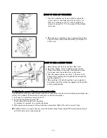
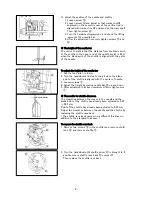
10] HOW TO INSTALL THE BOBBIN 

1. After pulling out thread approximately 10 cm
   from bobbin ① , put the bobbin into bobbin case
   ②.
2. Pass the thread through the threading groove Ⅰ
  in the bobbib case.

CAUTION: 

Fit the bobbin in the bobbin case so
that the bobbin turns in the direction
of the arrow when the bobbin thread
is pulled.

3. Pass the thread through thread slit Ⅱ and pull 
   it up.  Then the thread can be passed under the 
   thread tension spring ③ and pulled out.
4. Push the bobbin case into the original position
   of holding the bobbin.

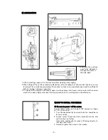
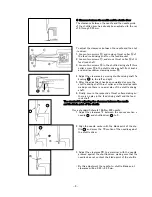
11] HOW TO THREAD THE MACHINE HEAD

1. Turn the handwheel by hand to move the 
    thread take-up lever to its top position.
2. Thread in the order illustrated and thread the
    needle from the left to the right.
3. Pull out the thread, which has been threaded 
   in the needle, approximately 10 cm.

CAUTION:

Thread the right-hand side of sec-
tion ⑧ when viewed from the face
plate.

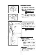
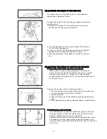
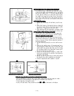
12] ADJUSTING THE STITCH LENGTH AND 
     REVERSE STITCHING

◆ Adjusting the stitch length


To adjusting the stitch length, use the feed 
regulator nut ① .
Align the upper end Ⅰ of the feed lever to the 
scale indicating the desired amount.
    To increase the pitch, turn the nut counter
    -clockwise.
    To decrease the pitch, turn the nut clock-
    wise.
   ( To decrease the stitch length, turn the nut
   while slightly pushing the feed lever down. )

◆ Reverse stitching

To carry out reverse stitching, push the feed
lever up by hand as far as it will go.
Reverse stitching can be done only when the 
feed lever is pushed up.

- 5 -

Summary of Contents for CS-471

Page 1: ...her person s head or fingers to come close to the handwheel V belt bobbin winder or moter Also do not place anything close to them 3 Do not run the machine with the finger guard belt cover or any other protectors removed Eye guard is option 4 Be sure to turn OFF the power switch and confirm that the motor is completely stopped before removing the V belt 5 Never remove the sewing machine from the t...

Page 2: ...hat connecting rod is at right angles to motor control lever Connect the connecting rod with pedal adjusting pla te so that the rod is also at right angles to the pedal The angle of the pedal The tilt of the pedal can be changed freely by adjus ting the length of the connecting rod To change the tilt of the pedal loosen the adjusting screw and advance or retract the connecting rod 5 CLEANING Waste...

Page 3: ...operation 3 To operate the machine continuosly apply two three drops of oil each section noted with an arrow mark in the above figure whenever starting operation in the morning and in the afternoon 7 HOW TO INSTALL THE NEEDLE Be sure to power off the motor The standard needle is a Schmetz 794 however an Organ DY 3 can be used 1 Turn the handwheel by hand and raise the needle bar to its top positio...

Page 4: ...own and the bobbin starts rotating to wind bobbin thread with the machine operated 5 When winding of bobbin thread has been completed the winder trip latch will be disengaged and the bobbin will stop autmatically Adjusting the amount of thread wound round the bobbin That amount of threa has already been adjusted so that thread can be wound round approximately nine tenths of the bobbin If the amoun...

Page 5: ...sition 2 Thread in the order illustrated and thread the needle from the left to the right 3 Pull out the thread which has been threaded in the needle approximately 10 cm CAUTION Thread the right hand side of sec tion when viewed from the face plate 12 ADJUSTING THE STITCH LENGTH AND REVERSE STITCHING Adjusting the stitch length To adjusting the stitch length use the feed regulator nut Align the up...

Page 6: ...he standard stroke of thread take up spring is 8 to 15 mm To adjust the operating range 1 Loosen screw 2 Adjust the operating range by moving thread the take up spring adjusting plate up and down 3 After adjustment has been completed tighten screw firmly 15 ADJUSTING THE PRESSER FOOT PRESSURE The standard height of presser spring regulator 30mm above the main unit surface The presser foot pressure...

Page 7: ...le and the shuttle race come in contact with each other at point Ⅰ a distance of 1mm should be provided between the blade point of the shuttle and end face Ⅱ of the shuttle race To adjust the position of the shuttle being pulled 1 Turn the handwheel and stop turning when the shuttle turns counterclockwise until it will go no further 2 Loosen screw 3 Align the blade point of the shuttle by turning ...

Page 8: ...d stop turning it when the blade point of the shuttle is aligned with the center of needle 3 Loosen screws 4 Adjust the height by moving needle bar up and down 5 After adjustment has been completed firmly tighten screw The needle to shuttle clearance The clearance between the recess in the needle and the blade point of the shuttle has already been adjusted to 0 25 0 35 mm Point of the shuttle has ...

Page 9: ...leted secure the shuttle driving shaft thrust collar and the small pendulu making sure there is no axial play of the shuttle driving shaft 6 Finally secure the respective thrust collars making su there is no play in the feed driving shaft and the feed rock shaft The standard for adjusting the clearance between the needle and the blade point of the shuttle Use a standard Schmetz 794 Nm 230 needle 1...

Page 10: ...d is not same as that at the sewing start perform t following adjustment 1 Loosen clamping screw in center shaft rear arm 2 Move center shaft rear arm toward away from y and temporarily tighten the screw At this time mov center shaft rear arm away from you to decrease the oscillating width of the needle bar frame or pull the arm toward you to increase it 3 Slowly turn the handwheel by hand to conf...

Page 11: ...screw 7 Loosen screws and and position needle bar frame presser retaining shaft and needle bar fram presser retaining plate to the position where the needle bar frame moves smoothly without play when needle bar frame presser plate is attached to the needle bar frame Then tighten the screws Caution After the needle entry point has been adjusted be sur to confirm the clearance between the needle and...

Page 12: ...memo 13 ...

Page 13: ...GOLDEN WHEEL CHEE SIANG INDUSTRIAL CO LTD No 32 Wu Chuan 7th Road Wu Ku Industrial Area Wu Ku Hsiang 24248 Taipei Hsien Taiwan Tel 886 2 2999518 Fax 886 2 2999519 ...

Page 14: ... the thread take Decrease the amount of movement of up spring is excessive the thread take up spring Overheated needle or shuttle Thread is not Use silicone oil pulled smoothly Reverse stitching is made at low speed on light Wind the needle weight material using nylon thread thread around the needle 3 Improper thread tension Poor finish of the thread path Smooth the surface with a fine paper irreg...

Reviews: