


Buzzaround XL_SG_REVA_100711
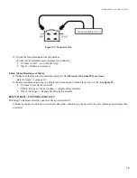
8
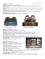
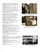
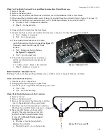
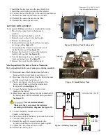
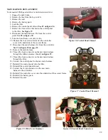
Component:
Speed Pot
Location:
Mounted on the control panel (12).
See #1 on figure 9.
Function:
The speed potentiometer (pot) uses variable resistance to control
the speed of the scooter.
Connections:
Connected to the main harness through the control panel harness.
Failure Signs:
Beep Code #7
Tests:
Call Tech Support
Expected readings:
Depends on speed pot position.
Serviceable:
No. Replace the control panel.
Component:
Key Switch
Location:
Mounted on the control panel (12).
See #2 on figure 9.
Function:
Completes the circuit to provide power to the motor.
Connections:
Connected to the main harness through the
control panel harness.
Failure Signs:
No power when the key is in the ON position.
Tests:
Continuity when the key is in the “ON” position. Make
sure the connector pins are seated properly.
Expected readings:
Less than 10 ohms.
Serviceable:
No. Replace the control panel.
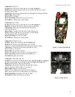
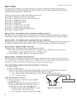
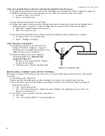
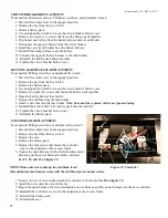
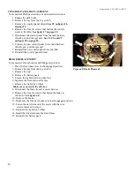
Component:
Throttle Pot (13)
Location:
Under the control panel.
See #1 on figure 10.
Function:
The throttle pot (potentiometer) uses variable
resistance to control speed and direction of travel by varying voltage.
Connections:
Connected to the control panel harness (12a).
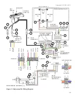
Figure 9. Control Panel (Back)
Refer to figure 11 on page 10.
Failure Signs:
Beep Codes #6 and #7.
Tests:
Test resistance across the pins 1, 2, and 3 and on 13a.
Expected readings:
Depends on direction of deflection.
Serviceable:
Replace as necessary.
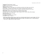
Component:
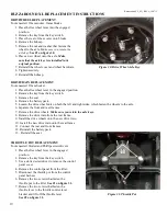
Charger Harness (14)
Location:
Two locations. Inside the battery pack.
See #14 on figure 3 on page 5.
Second charger harness located inside the tiller.
See figure 11 on page 10.
Function:
Connects the charger to the batteries.
Connections:
Connected to the battery harness (4a) and the
charger, not shown. Refer to figure 11 on page 10.
Failure Signs:
Batteries will not charge.
Tests:
Test for voltage and continuity. Check connectors.
Make sure the pins are not corroded and are seated properly.
Expected readings:
Continuity (less than 10 ohms).
Serviceable:
Replace the harness as necessary.
Figure 10. Throttle Pot
1
2
1