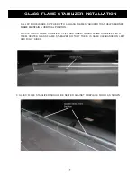
background image

14

FOR YOUR SAFETY READ BEFORE LIGHTING

WARNING:

 IF YOU DO NOT FOLLOW THESE INSTRUCTIONS EXACTLY,

A FIRE OR EXPLOSION MAY RESULT CAUSING PROPERTY DAMAGE,  
PERSONAL INJURY OR LOSS OF LIFE.

A.


This appliance is equipped with an ignition device which automatically lights the

pilot. Do not light pilot by hand.

B.


BEFORE LIGHTING smell all around the appliance area for gas. Be sure to smell

next to the 

 because some gas is heavier than air and will settle on the

WHAT TO DO IF YOU SMELL GAS:

• Do not try to light any appliance
• Do not touch any electric switch:
• Do not use any phone in your building.
• Immediately call your gas supplier from a neighbor’s phone. Follow the gas

supplier’s instructions

C.


Do not use this appliance if any part has been under water. Immediately call a

 service technician to inspect the appliance and to replace any part of 

the gas control system which has been under water.

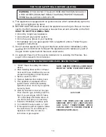
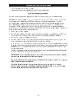
LIGHTING INSTRUCTIONS ELEC. SPARK TO PILOT

NOTE: DAMPER CONTROL LEVER MUST 

BE IN THE “OPEN” POSITION TO IGNITE.

GAS VALVE

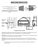
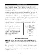
An approved Power Vent Fan must be installed prior to operating this Fireplace. See        

page 8 of this manual for fan information.

D.

1.

“STOP” Read  the safety information


above.

2.

After installing Enervex RS-14 Power


Vent and Proven Draft Switch you can


proceed with lighting of this Fireplace

3.

Set the  switch to “OFF”.

4.

Remove batteries from battery pack.

5. This 

appliance is equipped with an 

ignition


device which automatically 

lights the


burner. Do not try to light the 

burner


by hand.

6.

Wait (5) minutes to clear out any gas.


Then smell for gas, including near the


floor. 

If you smell gas, STOP! Follow 

“B” in


the safety information 

above

. If


you don’t smell gas, go to next step.

7.

Install (2) D batteries in battery pack.

8.

Turn ON/OFF rocker switch to " ON".

9.

If the appliance will not operate, follow


the instructions “To turn Off Gas To


Appliance” and call your service


technician or gas supplier.
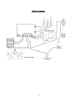
NOTE: 

THIS  FIREPLACE  CAN  ALSO  BE 

SERVICED  WITH  120V  JUNCTION  BOX 

AND  3-VOLT  TRANSFORMER  WHICH 

CAN  BE  USED  TO  PROVIDE  POWER  IF 

DESIRED (PART# JB-3V).

Summary of Contents for LFP9618

Page 1: ...S Z21 50 2014 WARNING THIS FIREPLACE MUST BE INSTALLED USING AN APPROVED POWER VENT FAN SEE INSTALLING CHIMNEY VENT SYSTEMS SECTION OF THIS MANUAL FOR APPROVED FAN MODELS AND SPECIFICATIONS MODEL LFP9618 POWER VENTED TOP VENT GAS FIREPLACE 2 21 ...

Page 2: ...ssure Requirements 5 Installation Instructions 6 9 Lighting Instructions 14 15 Trouble Shooting 16 17 Replacement Parts 18 2 INSIDE ROOM FLUSH MOUNT CHASE INSTALLATION OPTIONS Figure 2 1 Glass Installation Flame Stabilizer Installation 10 11 Maintenance Instructions Wiring Diagram 12 13 Operating Guidelines 12 ...

Page 3: ...TERIOR VIEW Left Outside Air Control Damper Control Lever Pilot Assy Flame Sensor Right Outside Air Control On Off Switch LEFT RIGHT 3 Valve Access Door OUTSIDE AIR CONNECTIONS LFP9618 COMPONENT LOCATIONS ...

Page 4: ...2014 The design of this FIREPLACE has been tested and is listed with PFS CORPORATION in accordance with THE AMERICAN NATIONAL STANDARDS INSTITUTE ANSI Z21 50 2014 This manual serves only as a basic guideline for installation and use of this and gas piping The complete installation must be in accordance with local codes and ordinances or in the absence of local codes with the American National Stan...

Page 5: ...S LEAKS AT THE CONTROL WITH POSSIBLE FIRE OR EXPLOSION Include a manual shut off valve and union in the line so the control or heater may be disconnected for servicing Include a drip leg and a plugged 1 8 N P T tapping into the line also The tapping must be accessible for the test gauge connection immediately upstream of the gas supply connection to the unit Use a soap and water solution or liquid...

Page 6: ...cted of 2 x 4 lumber or heavier The framing headers may rest on the standoffs Refer to Figure 7 1 for and framing reference dimensions CAUTION VERIFY FIREPLACE DIMENSIONS FRAMING METHODS AND WALL COVERING DETAILS BEFORE FRAMING CONSTRUCTION BEGINS Determine the exact position of the so that the vent run can be planned Figure 2 1 shows possible locations for the inside of a room mount in a chase Us...

Page 7: ... DIMENSIONS LFP9618 LFP 9618 A 106 B 111 C 96 D 104 3 4 Model LFP9618 is approved to be used with 10 B Type Gas Vent The Fireplace must be installed with an Enervex Model RS 14 Exhaust Fan PDS 1 or ADC 100 Draft Switch that is connected to this Fireplace WARNING This Fireplace must not be installed without Exhaust Fan Golden Blount Inc can supply the Enervex products or they can be purchased throu...

Page 8: ...VENT EXHAUST FAN 1 800 833 1134 WARNING This gas appliance must not be connected to a chimney flue serving a separate solid fuel burning appliance Note a draft hood is installed and is in the same atmospheric pressure zone as the combustion air inlet to the appliance and is located so that the relief opening is accessible for checking vent operation Minimum Vent Length 5 Maximum Vertical Run 50 Ma...

Page 9: ... choice Do not install a combustible mantle or other combustible projection above the opening unless it is a minimum of 12 inches above top of opening Figure 9 2 CAUTION All joints between the wall and the surround Top and Sides can only be sealed with non combustible material Only non combustible material can be applied as facing to the surround Figure 9 2 Hearth Extension A Hearth Extension may ...

Page 10: ...d Fireglass to enhance the overall appearance 2 Fill the burner tray below and up to the top of the burner ports Do not cover burner ports 3 Distribute additional glass around front sides and rear of burner tray covering floor area Figures 10 1 10 2 GLASS INSTALLATION CONT Figure 10 2 ...

Page 11: ...ER THAT HELPS BURNER FLAME MAINTAIN A VERTICAL POSITION LOCATE GLASS FLAME STABILIZER CLIPS AND INSERT GLASS FLAME STABILIZER INTO THEM CENTER GLASS FLAME STABILIZER SO THAT THERE IS SAME CLEARANCE ON LEFT AND RIGHT SIDES 3 GLASS FLAME STABILIZER SHOULD BE SEATED AGAINST FIREPLACE FLOOR AS SHOWN ...

Page 12: ...E BEGINNING OF EACH HEATING SEASON WARNING THE FLOW OF COMBUSTION AND VENTILATION AIR MUST NOT BE OBSTRUCTED When lit for the time the appliance will emit a slight odor for an hour or two This is due to paint and lubricants used in the manufacturing process The main burner characteristics are steady not lifting or Typically the top 1 4 inch of the sensor should be engulfed in the pilot A periodic ...

Page 13: ...13 WIRING DIAGRAM see below 6003 3V Model Different valve may use pin connector 6003V 6K Model ...

Page 14: ...EC SPARK TO PILOT NOTE DAMPER CONTROL LEVER MUST BE IN THE OPEN POSITION TO IGNITE GAS VALVE An approved Power Vent Fan must be installed prior to operating this Fireplace See page 8 of this manual for fan information D 1 STOP Read the safety information above 2 After installing Enervex RS 14 Power Vent and Proven Draft Switch you can proceed with lighting of this Fireplace 3 Set the switch to OFF...

Page 15: ... DO NOT use a telephone inside of building 3 Shut off gas at L P tank outside of building 4 Telephone gas company and department Ask instructions Before hanging up give your name address and phone number DO NOT go back into building If your L P tank runs out of fuel turn off gas at the appliance After L P tank is appliance TO TURN OFF GAS TO APPLIANCE must be re lit according to manufacturer s ins...

Page 16: ...16 Enervex Fan not operating and connecting Draft Switch to operate Fireplace 9 Check to see if Enervex Fan is running and Draft Switch is closing Fireplace circuit 9 13 ...

Page 17: ...17 ...

Page 18: ...REPLACEMENT PARTS THE FOLLOWING REPLACEMENT PARTS ARE AVAILABLE FROM YOUR GOLDEN BLOUNT DEALER 1 2 3 6 10 11 12 16 15 4 14 13 18 7 8 ...

Page 19: ...19 Inc ...

Reviews: