


Hardware
3-6
basicCAN 61 PLUS – User Manual
The
basicCAN 61 PLUS
has two (optionally up to six) Communication
interfaces, designed as CAN 2.0B interfaces using the TJA1041A
Highspeed CAN Transceiver.
Optionally it is possible to plug in different/ further transceivers
(totally 4, that means not for the CAN Extension board).
By the type of the plugged-in transceivers you decide the performance
of the assigned interfaces!
For changing or plugging in additional transceivers,
open the stand-alone device (with the system switched off).
To do that, unscrew and remove the four upper screws of the frontal
and rear plates, and unscrew slightly the four lower screws
(until the upper cover can be removed). Please proceed extremely
carefully, otherwise the device could be damaged.
When plugging in transceivers, please attend to their correct position
and orientation.
In the case of further inquiries, please contact our support
department ([email protected]).
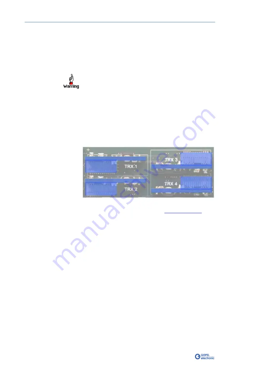
The position and orientation of the transceivers
can be seen in the following figure:
Each transceiver type is coded and can be identified clearly.
For the available types of transceivers, see
As a rule all four interfaces are supplied by an internal voltage
of 12V (UBAT
int
) generated from
ext. Power Supply
(see Figure 3-3).
In case of using other voltages for the interfaces,
this internal voltage can be switched off individually by software
(G-API commands
G_Can_Node_InternalVBat_Disable
G_Lin_Node_InternalVBat_Disable
or
G_KLine_Node_InternalVBat_Disable
).
Then, an external voltage (UBAT
ext
) must be supplied via the
predefined pins of the corresponding frontal connector
Node 1..4
.
In case the internal power supply has to be used again later,
execute the G-API commands
G_Can_Node_InternalVBat_Enable
G_Lin_Node_InternalVBat_Enable
or
G_Kline_Node_InternalVBat_Enable
.
3.5.4
OnBoard
Interfaces
Figure 3-5:
Transceiver positions


