MAINTENANCE MANUAL
GP/146/99. Issue 9. October 2005
The silicon carbide ring fitted in the rear side of the HP impeller may be levered out,
by means of a small instrument screwdriver inserted between the ring and its rubber
cup.
Reassembly of the seal is completed as described below. Please note: Mechanical
Seals are precision engineered devices and extreme care must be taken to ensure
that no damage occurs to the lapped faces.
Read the fitting instructions before installation of the seal.
Ensure that the lapped faces are absolutely clean throughout the entire
installation.
Soiled faces must to be cleaned with appropriate degreasing cleaner
and soft tissue.
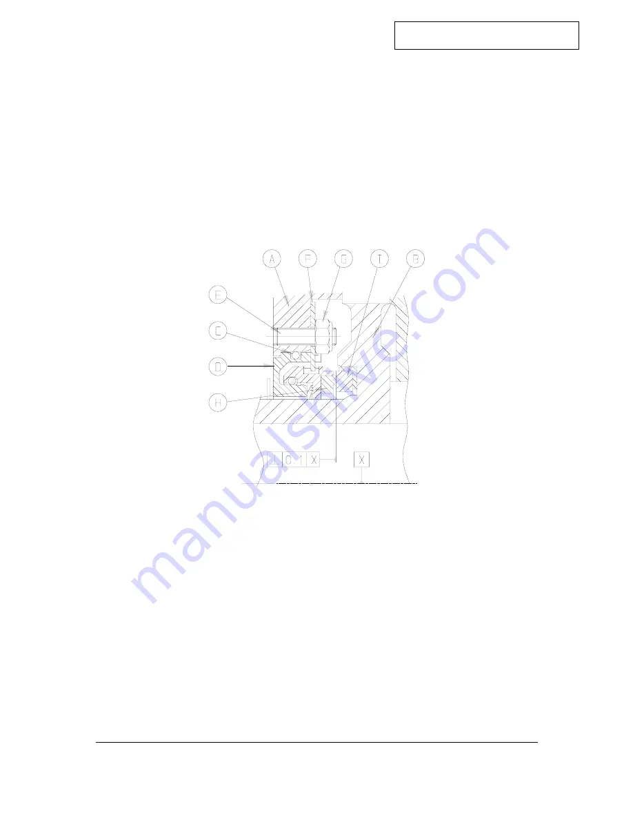
Fig 5-1Carbon seal
and seating assembly
1. Ensure that the Pump Body (A) and High Pressure Impeller (B) bores are clean
and free from burrs and sharp edges , see Fig 5-1.
2. Lubricate the O Ring (C) with a suitable lubricant and carefully assemble the
Seal Head Assembly (D) into the Pump Body (A), lining up the cutouts in the
Seal Head Assembly (D) with the threaded Studs (E).
3. Fit Washer (F) to each of the Studs (E) followed by the Lock Nuts (G). The lock
nuts should be tightened half a turn at a time so that the Seal Head Assembly
(D) is pulled squarely into the Engine Housing. Ensure that the Lock Nuts are
fully secured.
4. Ensure Carbon Face (H) is clean and free from grease, if not use a degreasing
cleaner and soft tissue. Apply clean water to the carbon face.
5. Take Impeller (B) and carefully push the Mating Ring Assembly (I) into the bore
using Fitting Tool Number 60275/08. Ensure that the Face of the Mating Ring
Assembly is fitted squarely in the impeller housing within 0.1mm.
6. Carefully fit the High Pressure Impeller onto the shaft and continue with pump
build.
©Hale Products Europe LTD, Warwick
GP/146/99
WTmaint - Issue9. 10-2005October 2005
17


