background image

EZ300 Series

2

1-2

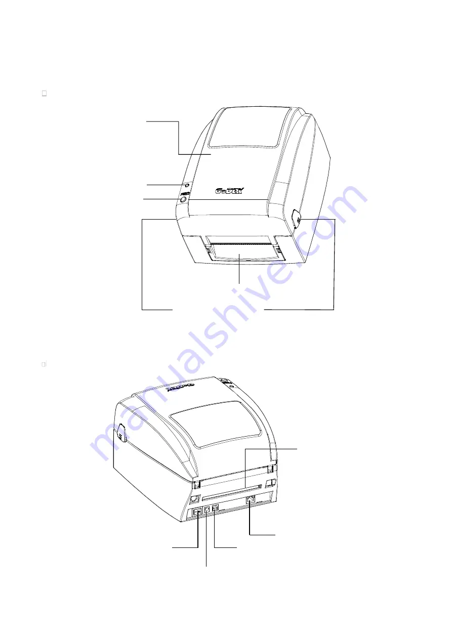
Getting To Know Your Printer

Front View

Rear View

TOP COVER

LED INDICATOR

FEED BUTTON

FRONT COVER

COVER OPEN

BUTTONS

POWER SWITCH

FAN-FOLD LABEL INSERT

ETHERNET PORT

USB PORT

POWER JACK

Summary of Contents for EZ-1105P series

Page 1: ...EZ 1105P series BARCODE PRINTER USER MANUAL User Manual EZ 1105P series Version A Issue Date 2014 12 P N 920 015511 00 ...

Page 2: ...rinting 15 2 9 Connecting The Printer To The Host Computer 16 2 10 Installing The Driver 17 3 Operation Panel 20 3 1 LED Operation Panel 20 3 2 Error Alerts 21 3 3 Label size calibration and Self Test Page 22 3 4 Operation Panel 23 4 NetSetting for Ethernet 24 4 1 Installing The NetSetting software 24 4 2 The interface of NetSetting 25 5 Maintenance And Adjustment 32 5 1 Cleaning The Print Head 32...

Page 3: ...s equipment has been tested and passed with the requirements relating to electromagnetic compatibility based on the standards EN 55022 2006 A1 2007 Class A EN61000 3 2 2006 EN 61000 3 3 2008 and EN55024 1998 A1 2001 A2 2003 IEC 61000 4 2 2008 series The equipment also tested and passed in accordance with the European Standard EN55022 for the both Radiated and Conducted emissions limits EZ100 EZ 11...

Page 4: ...e 5 Be careful not to get liquid on the equipment to avoid electrical shock 6 For safety and warranty reasons ONLY qualified service personnel should open the equipment 7 Do not repair or adjust energized equipment under any circumstances CAUTION Danger of explosion if battery is incorrectly replaced Replace only with the equivalent type recommended by the manufacturer Dispose of used batteries ac...

Page 5: ...hat all of the following items are included with your printer Barcode Printer Ribbon Hubs set of 2 Power Adapter AC Adapter Label Supply Hub USB Cable Label Guide Plates set of 2 Ribbon Quick Guide Label Stock Empty Ribbon Core CD with GoLabel software user manual ...

Page 6: ...Z300 Series 2 1 2 Getting To Know Your Printer Front View Rear View TOP COVER LED INDICATOR FEED BUTTON FRONT COVER COVER OPEN BUTTONS POWER SWITCH FAN FOLD LABEL INSERT ETHERNET PORT USB PORT POWER JACK ...

Page 7: ...UPPLY HUB LABEL GUIDE PLATES SET of 2 ADJUSTMENT SCREW RIGHT Screw for adjusting the print head pressure RIBBON MODULE RIBBON FEED MECHANISM RIBBON HUB EMPTY RIBBON CORE LABEL GUIDE LEFT ADJUSTMENT SCREW Screw for adjusting the print line LABEL GUIDE RIGHT PLATEN LABEL SENSOR Movable RIBBON SUPPLY HUB PRINTING MECHANISM RELEASE CATCH RIGHT RELEASE CATCH LEFT ...

Page 8: ...ons Place the printer on a flat surface Open the printer cover by pressing the release buttons on both sides of the printer housing and lift the cover COVER OPEN BUTTONS Release buttons for opening the printer cover Pressing the button Pressing the button Lift the printer cover backward ...

Page 9: ...EZ300 Series 5 2 2 Open The Printing Mechanism Pressing The Release Catches Release and lift the printing mechanism Pressing Pressing Lift the printing mechanism RELEASE CATCHES ...

Page 10: ...y hub Place the empty ribbon core on the hub which forms a ribbon rewind hub Stick the ribbon supply hub on the ribbon rewind hub and wind the rewind hub 2 3 circles NEW RIBBON RIBBON HUB Place on the hub RIBBON SUPPLY HUB EMPTY RIBBON CORE RIBBON HUB Place on the hub RIBBON FEED MODULE Wind the ribbon around the core 2 3 circles ...

Page 11: ...printing mechanism Pass the ribbon supply hub under the print head Insert the ribbon rewind hub on the ribbon feed mechanism Close the printing mechanism making sure that it clicks into place Insert into the printing mechanism Place on the printing mechanism RIBBON FEED MECHANISM Wind to the back ...

Page 12: ...on Place the label stock on the label supply hub attach the guide plates to the label stock holder Install The Label Roll Module On The Printer Now load the label stock into the printer LABEL STOCK Place on the ribbon hub Place on the printer LABEL SUPPLY HUB LABEL GUIDE PLATES ...

Page 13: ...ase the printing mechanism and lift it Pass the labels through the label guides up to the tear off plate Adjust the label guides to the label width Close the printing mechanism Through the label guides LABEL GUIDES Close ...

Page 14: ...ll Label Dispenser Model Pass the paper through the guides Remove the first labels from the liner so you can pull the liner through the guides Through the label guides LABEL GUIDES THE PAPER FEED ROLLER OF PRINTER Tear a label THE FIRST LABEL ...

Page 15: ...he printer as shown in the illustration on the right Close the label dispenser and the print mechanism The installation is completed now LABEL STOCK THE PAPER FEED ROLLER OF PRINTER THE PAPER FEED ROLLER OF LABEL DISPENSER MODULE LINER LABEL Close ...

Page 16: ...ll take labels up to a max width of 110 mm Labels should be at least 25 mm high to ensure correct functioning of the label dispenser When using the label dispenser set the stop position to 9 mm There is a paper sensor on the Label Dispenser module It will stop the printing if it is covered by label Please remove the last printed label and the printer will then continue to print next label Press th...

Page 17: ...a blade life of 400 000 cuts when using paper liner which is 0 2mm thick and 3 inches wide You can cut paper with a max width of 116 mm Labels should be at least 30 mm high to ensure correct functioning of the cutter With the cutter installed setting the stop position in GoLabel to 30 or the E value to 30 is recommended If you use cutter please do not use inside wound media while printing otherwis...

Page 18: ...7 Installing The Label Supply Hub Base On Internal Diameter 1 Cores Installing the label supply hub for 1 cores 1 5 Cores Installing the label supply hub for 1 5 cores 3 Cores Installing the label supply hub for 3 cores ...

Page 19: ...8 Preparing For Tag Printing In tag printing the tag hole indicates the height of a label During adjustment the sensor must therefore be positioned directly below the tag hole as shown in the illustration SENSOR POSITION ...

Page 20: ...adapter and connect the adapter to the printer Connect the USB parallel cable to the printer and host computer USB parallel cable s type depends on the printer which you purchase Switch on the printer The LED indicator should now lights up B1 USB PORT B1 USB PORT A1 POWER SLOT A1 POWER JACK A2 PLUG A2 THE SOCKET OF THE WALL B2 USB PORT B2 USB PORT ...

Page 21: ...open the Seagull Driver folder on the CD STEP 02 Select the icon for the driver file and click it to start the installation STEP 03 Follow the instructions on the screen The Driver Wizard guides you through the installation procedure STEP 04 Select Install printer drivers STEP 05 Specify your printer model Godex EZ520 ...

Page 22: ...sign the appropriate rights STEP 08 Once the installation is complete a summary of the printer settings is displayed STEP 09 Check whether the printer settings are correct and click Finish to start copying the driver files STEP 10 Wait until copying is complete then finish the installation Godex EZ520 Godex EZ520 Godex EZ520 ...

Page 23: ...EZ300 Series 19 STEP 11 Once the driver installation is complete the new printer should appear in the Printers and Faxes folder Godex EZ520 Godex EZ520 ...

Page 24: ...f you are using individual labels pressing the FEED button will move only one label If the label does not stop at the correct position please run the auto calibration See Section 3 2 for the label size calibration function on the label stock LED Indicators LED indicator Status Description Green Standby mode The printer is ready for operation Red Orange Error mode The printer has detected an error ...

Page 25: ...ermal printing mode 1 To work in thermal transfer mode load a ribbon 2 Alternatively select the direct thermal printing mode First 2 beeps than 3 beeps Memory Error The memory is full The printer prints the message File System full Delete unnecessary data from memory Unable to find file The printer prints the message File Name Not found Use the X4 command to print all files Then check whether the ...

Page 26: ...self test printout are listed below Model Version IP address of Ethernet port Gateway setting Netmask setting Number of DRAM installed Image buffer size Number of forms Number of graphics Number of fonts Number of Asian fonts Number of Databases Number of Scalable fonts Free memory size Speed Density Ref Point Print direction Label width Form length Stop position Cutter Label Dispenser Mode Sensor...

Page 27: ... single beep Release FEED key when heard the 3rd beep STEP 2 Make sure Printer ready for print a label STEP 3 Send a label or commands which met problem to the printer STEP 4 Printer will print out a label with letters and numbers please take a picture on them and send us by email To cancel get out of the Dump Mode please press the FEED key and then the printer will automatically print OUT OF DUMP...

Page 28: ...w below steps Step 01 Insert the product CD in the CD DVD drive of the host computer and open the Ethernet folder on the CD Step 02 Select the icon for the NetSetting installation file and click it to start the installation Step 03 Follow the instructions on the screen The Setup Wizard guides you through the installation procedure Step 04 Specify the Installation Folder Step 05 Click Next to start...

Page 29: ... basic information of connected printer and your PC Click the magnifier icon to search the Godex printers which are connected via Ethernet port in you network environment Once a connected Godex printer is detected it will be listed on the start page There are six tabs on the top of interface which can configure different types of network settings But for the data ...

Page 30: ...er name Port number Gateway setting and the password for configuring the printer You can also set the printer s IP address ether by DHCP or by Static IP You can press Set button to apply the settings and ReGet button to refresh the setting values NOTICE To fully benefit from the NetSetting software you should be familiar with basic networking principles Please contact your network administrator fo...

Page 31: ...ror happened on printer The alert messages are sent by SMTP Simple Mail Transfer Protocol or SNMP Simple Network Management Protocol You can set or change the configurations of SMTP and SNMP on this Alert Path Setting tab You can press Set button to apply the settings and ReGet button to refresh the setting values ...

Page 32: ...ge notification function you can decide which error cases need to be sent out to the operator Moreover the alert messages can be set to be sent by SMTP SNMP or both You can press Set button to apply the settings and ReGet button to refresh the setting values ...

Page 33: ...ation Set or change the configurations of connected printer Most of key settings for the printer operation can be done by this setting page You can press Set button to apply the settings and ReGet button to refresh the setting values ...

Page 34: ...printer commands in Input Command window and press Send Command button the commands will be sent to the printer For some commands that will return response message the message will be displayed in Output Message window You can press Send Command button to send printer commands via Ethernet port and control the printer remotely ...

Page 35: ... If you need to update the printer firmware just specify the file location of firmware file and press Start Download Firmware button The printer firmware then can be updated remotely In addition to the firmware update you can press Recover To Factory Settings button to restore the printer configurations back to factory default ...

Page 36: ...nger lifespan of the print head Cleaning Steps Here is how you clean the print head 1 Switch off the printer 2 Open the printer cover 3 Release the printing mechanism and lift it 4 Remove the ribbon 5 To remove any label residue or other dirt from the print head see blue arrow please use a soft lint free cloth dipped in alcohol NOTICE The print head should be cleaned once a week Please make sure t...

Page 37: ... Turn towards Minus indicates The pressure is reduced 5 3 Adjusting The Print Line When the print line is incorrectly set the print quality on one side of the medium may suffer In such a case the print line must be adjusted so it is positioned parallel to the paper feed roller Adjustment Methods 1 To move the print head in direction A as indicated by the blue arrow turn the adjustment wheel anticl...

Page 38: ... located on the bottom of cutter module as shown in below illustration Cleaning Steps 1 Switch off the printer 2 Use a Philips screwdriver to turn the socket head screw and release the knife 3 When you have cleared the paper jam switch on the printer again The cutter will automatically reset NOTICE Labels should be at least 30 mm high to ensure correct functioning of the cutter SOCKET HEAD SCREW ...

Page 39: ...or ribbon residue Check for errors in the application software Check the ribbon for wrinkles Check the power supply Run a self test Section 3 2 and check the test print pattern to see whether the print head prints over the entire width of the medium Check the quality of the print medium The printed image is positioned incorrectly or a label is missed out during printing Run the Label size calibrat...

Page 40: ... 39 Code 93 EAN 8 13 add on 2 5 UPC A E add on 2 5 I 2 of 5 I 2 of 5 with Shipping Bearer Bars Codabar Code 128 subset A B C EAN 128 RPS 128 UCC 128 UCC EAN 128 K Mart Random Weight Post NET ITF 14 China Postal Code HIBC MSI Plessey Telepen FIM GS1 DataBar German Post Code Planet 11 13 digit Japanese Postnet I 2 of 5 with human readable check digit Standard 2 of 5 Industrial 2 of 5 Logmars Code 11...

Reviews: