background image

Safety
Instructions

12. POWER-CORD PROTECTION - Power-supply cords should be routed so that

they are not likely to be walked on or pinched by items placed upon or against
them, paying particular attention to cords of plugs, convenience receptacles,
and the point where they exit from the unit.

13. OUTDOOR ANTENNA GROUNDING - If an outside antenna or cable system is

connected to the video unit, be sure the antenna or cable system is grounded to
provide some protection against voltage surges and built-up static charges.
Section 810 of the National Electrical Code, ANSI/NFPA No. 70-1984, provides
information with respect to proper grounding of the mast and supporting
structure, grounding of the lead-in wire to an antenna discharge unit, size of
grounding conductors, location of antenna-discharge unit, connection to
grounding electrodes, and requirements for the grounding electrode. See Figure
on this page.

14. LIGHTNING - For added protection of this video unit during a lightning storm, or

when it is left unattended and unused for long periods of time, unplug it from
the wall outlet and disconnect the antenna or cable system. This will prevent
damage to the video unit due to lightning and power line surges.

15. POWER LINES - An outside antenna system should not be located in the vicinity

of overhead power lines or other electric light or power circuits, where it can
fall into such power lines or circuits. When installing an outside antenna system
extreme care should be taken to keep from touching such power lines or
circuits as contact with them might be fatal.

16. OVERLOADING - Do not overload wall outlets and extension cords as this can

result in the risk of fire or electric shock.

17. OBJECTS AND LIQUIDS - Never push objects of any kind into this video unit

through openings as they may touch dangerous voltage points or short out parts
that could result in a fire or electric shock. Never spill liquids of any kind onto
the unit. Should spillage occur, unplug unit and have it checked by a technician
before use.

18. SERVICING - Do not attempt to service this video unit  yourself as opening or

removing covers may expose you to a dangerous voltage or other hazards. Refer
all servicing to qualified service personnel.

19. DAMAGE REQUIRING SERVICE - Unplug this video unit from the wall outlet and

refer servicing to qualified service personnel under the following conditions:
a. When the power supply cord or plug is damaged.
b. If any liquid has been spilled onto or objects have fallen into the video unit.
c. If the video unit has been exposed to rain or water.
d. If the video unit does not operate normally by following the operating
instruction. Adjust only those controls that are covered by the operating
instructions. Improper adjustment of other controls may result in damage and
will often require extensive work by a qualified technician to restore the video
unit to its normal operation.
e. If the video unit has been dropped or the cabinet has been damaged.
f.

When the video unit exhibits a distinct change in performance — this

indicates a need for service.

20. REPLACEMENT PARTS - When replacement parts are required, be sure the

service technician has used replacement parts specified by the manufacturer or
have the same characteristics as the original part. Unauthorized substitutions
may result in fire, electric shock or other hazards.

21. SAFETY CHECK - Upon completion of any service or repairs to this video unit

ask the service technician to perform safety checks to determine that the video
unit is in safe operating order.

GROUND
CLAMP

ELECTRIC
SERVICE
EQUIPMENT

GROUND
CLAMPS

ANTENNA
LEAD-IN
WIRE

ANTENNA
DISCHARGE
UNIT (NEC
SECTION 810-20)

GROUNDING CONDUCTORS
(NEC SECTION 810-21)

POWER SERVICE GROUNDING
ELECTRODE SYSTEM
(NEC ART 250, PART H)

NEC - NATIONAL ELECTRICAL CODE

2

Summary of Contents for GV2020

Page 1: ...Video Cassette Recorder Model GV2020 Owner s Guide Dual Deck...

Page 2: ...riques ne pas utiliser cette fiche polaris e avec un prolongateur une prise de courant ou une autre sortie de courant sauf si les lames peuvent etre ins r es fond sans en laisser aucune partie d couve...

Page 3: ...ge is only for 30 days from original date of pur chase WHAT ARE THE EXCEPTIONS This warranty does not cover 1 Damage from misuse abuse neglect or accident natural disasters or Acts of God 2 Cabinetry...

Page 4: ...excessive force and uneven surfaces may cause the appliance and cart combina tion to overturn PORTABLE CART WARNING Symbol provided by RETAC Safety Instructions 9 VENTILATION Slots and openings in the...

Page 5: ...touch dangerous voltage points or short out parts that could result in a fire or electric shock Never spill liquids of any kind onto the unit Should spillage occur unplug unit and have it checked by...

Page 6: ...ol and Front Panel 22 Video Menu Record Speed AmeriChrome Copy Auto Features 23 Audio Menu Dolby NR Audio Source 24 Set Date and Time 25 Channel Tuner Menu 26 27 On Screen Display 28 Front Panel Displ...

Page 7: ...e segment on a tape with Picture Scan or Jet Search Page 12 Picture Scan lets you view the tape at up to 9 times the normal play speed and Jet Search at up to 21 times the normal play speed in forward...

Page 8: ...n lead use the supplied adapter A cable is supplied with your VCR 2 Connect the coaxial round end of this cable to the Out to TV connection on your VCR 2 back panel Connect the other end of the suppli...

Page 9: ...ress to erase any changes you have made in the Set Date and Time Menu or Timer Recording Menu Front Panel Display Displays the status of your VCR 2 See the detailed explanation on page 29 FWD Fast For...

Page 10: ...eparate controls for Decks 1 and 2 Source Buttons Press to select the video source to be recorded on each deck Changes the Source indicators Source Indicators Indicate the video source that is being o...

Page 11: ...a complete description of the features mentioned in this section consult the Index pages 42 43 Neon light may disrupt the signal from the Remote Control Keep neon lights away from your VCR 2 and Remot...

Page 12: ...n and settings during On Screen Programming Pause Buttons Press to temporarily stop the tape while playing or recording Should not be used for more than 3 minutes at a time Your VCR 2 will Auto Stop a...

Page 13: ...d and Numeric buttons you can change the channel on your VCR 2 tuner The Numeric buttons are also used for setting the clock calendar and timer The Display button displays the On Screen Display on you...

Page 14: ...d Picture Scan FF will blink on the Front Panel Display Press Rewind for reverse Picture Scan REW will blink on the Front Panel Display Press Play to end forward or reverse Picture Scan and resume pla...

Page 15: ...o use AmeriChrome Copy 2 the original tape must be in Deck 1 and have been recorded at SP or LP speed When using AmeriChrome Copy 1 you can change the speed of the recording to fit more programming on...

Page 16: ...SP Standard Play or LP Long Play See page 23 See pages 34 36 to record one channel while viewing another and for recording when your VCR 2 is connected to a cable system Neither the Source nor the ch...

Page 17: ...h and select it last Turn on your TV and your VCR 2 and the second tuner if different from your TV Insert blank cassettes into Deck 1 and Deck 2 Use the Remote Control or Front Panel to choose the cha...

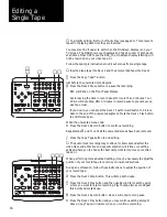
Page 18: ...the Copy Tape button to end editing The audio track recording may continue for a few seconds after the video track ends Practice and experimentation will refine your editing skills and help you to cho...

Page 19: ...on to pause the recording REC will blink on the Front Panel Display Avoid leaving the deck in record pause for more than 3 minutes Your VCR 2 will Auto Stop after 5 minutes in record pause to prevent...

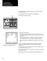
Page 20: ...ge the duration at any time during OTR by pressing Record 30 minutes will be added to the remaining time each time you press Record You can record even if your TV is turned off The channel indicated o...

Page 21: ...se the event number you wish to program or use the Up Down buttons to highlight your selection and press Next to choose it You ll see the Timer Recording Menu Use Previous and Next to move from one se...

Page 22: ...imulcast or SAP broadcasts use the Audio Menu to place the tuner in the appropriate mode See page 24 When Simulcast is active SC will appear after the channel number in both the Timer Recording Summar...

Page 23: ...recording will stop and the timer settings will be cleared if the event was a Normal event Daily and Weekly events will be updated automatically for the next date that was programmed If an event is no...

Page 24: ...settings Main Menu All other On Screen Programming menus are accessed through the Main Menu Press Menu The Main Menu will appear on your TV screen Press the Numeric buttons to choose your selection or...

Page 25: ...d Play unless you change the recording speed SP Standard Play provides the best picture LP Long Play provides twice the recording time of SP EP provides three times the recording time of SP and the be...

Page 26: ...in stereo otherwise the sound is mono SAP produces Second Audio Program sound usually a second language All SAP broad casts are mono TV SAP produces normal sound from one speaker and SAP sound from th...

Page 27: ...sired press Reset to return all entries to current time and continue with step You can do this at any time Press Save to accept your settings and return to the Main Menu You can do this at any time OR...

Page 28: ...l also switch to the appropriate Channel Memory One memory is for TV the other for STD CATV IRC CATV and HRC CATV Any changes made in one memory will not affect the other To automatically program Chan...

Page 29: ...Press Save or Escape to return to the Main Menu To add all channels to Channel Memory Follow steps and on the preceding page Use the Up Down buttons to highlight Add All Press Next to add all the chan...

Page 30: ...if the Memory Stop mode is active OTR and duration are displayed when One Two Recording is in progress AmeriChrome Copy Indicator Indicates that AmeriChrome Copy duplication is in progress Source Indi...

Page 31: ...such as REC when a recording is in progress Deck Status is blank if that deck does not contain a tape LINE This indicator reserved for future use MONO Indicates that the Audio Source is set to Mono O...

Page 32: ...cancel Auto Power Off Auto Power On Power turns on when a tape is inserted into either deck The TV VCR indicator switches to VCR Auto Rewind Your VCR 2 will automatically rewind when the end of the t...

Page 33: ...select that deck using the TV View buttons Press Reset The Tape Counter will be reset to 0000 for that deck the Tape Counter of the other deck will not be affected To reset the Tape Counter of the ot...

Page 34: ...ur TV Use a VHF UHF splitter not included if your TV has separate VHF and UHF inputs There are numerous possibilities for connecting your VCR 2 your TV your antenna or cable system your other video eq...

Page 35: ...connection A cable is supplied with your VCR 2 Connect the coaxial round end of this cable to the Out to TV connection Connect the other end of the supplied cable to the combined VHF UHF input on you...

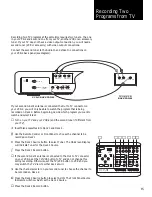
Page 36: ...l and view another follow these additional steps Begin recording the channel you are viewing see page 14 Switch your TV VCR button to TV Select the viewing channel with your TV channel selector 34 1 2...

Page 37: ...Set the VCR 2 back panel switch to either channel 3 or 4 choosing the one that you did not use for your cable system in above Set your TV tuner to the same channel used in above The above instruction...

Page 38: ...channel follow these instruc tions Turn on your TV VCR 2 and converter Set the TV to channel 2 3 or 4 whichever is used by your cable system Set the TV VCR selector to TV On both the VCR 2 and the con...

Page 39: ...TV IN FROM ANTENNA CABLE CH 3 CH 4 VCR 2 BACK PANEL VIDEO IN OUT RIGHT AUDIO OUT LEFT RIGHT AUDIO IN LEFT STILL TRACKING DECK 1 DECK 2 TO VIDEO EQUIPMENT AUDIO OUTPUT TO VIDEO EQUIPMENT VIDEO OUTPUT C...

Page 40: ...R 2 Set the Audio Source to Simulcast See page 24 Select the desired TV channel on the VCR 2 Tune the stereo receiver to the proper frequency to receive the audio transmission To record a Simulcast in...

Page 41: ...our VCR 2 on the monitor it may be necessary to switch the monitor to Video AUX or AV IN Refer to your monitor s owners manual for instructions When this connection style is used the TV VCR setting on...

Page 42: ...ad life Cleaning by any means other than a cleaning tape will void your warranty Care of Video Tapes Do not expose tapes to direct sunlight extreme heat or extreme cold Do not disassemble any cassette...

Page 43: ...RCA 1 0 V p p 75 ohms unbalanced OUTPUT Video Out connection RCA 1 0 V p p 75 ohms unbalanced HORIZ RES Color Monochrome more than 230 lines S N RATIO Better than 43 dB AUDIO INPUT Audio In connection...

Page 44: ...30 31 Menu Button 6 9 Index 42 Adapter 5 10 AmeriChrome Copy 13 AmeriChrome Copy Indicator 28 Antenna Connections 32 33 Antenna Source 26 Audio In and Out 15 37 38 Audio Menu 24 Audio Source 24 Auto...

Page 45: ...led Channels 32 Second Audio Program SAP 24 Service 44 Back Cover Index 43 Set Date and Time Menu 25 Setting the Timer 19 21 Priorities 21 Sharpness Control 7 12 Simulcast 24 38 Source 14 Source Butto...

Page 46: ...wer off then on again If this does not correct the problem refer to the resetting instructions at the top of the page Is Timer Recording or Rewind in progress Page 30 Auto Power Off The VCR 2 must be...

Page 47: ...17 United States Code Sections 501 and 506 Thisproductisnotmadeorsoldforunauthorizedrecording orplaybackofcopyrightedworks including withoutlimitation unauthorized recording from pre recorded copyrig...

Reviews: