Operation Manual
11
6.3 Mi c r op h on e S e t
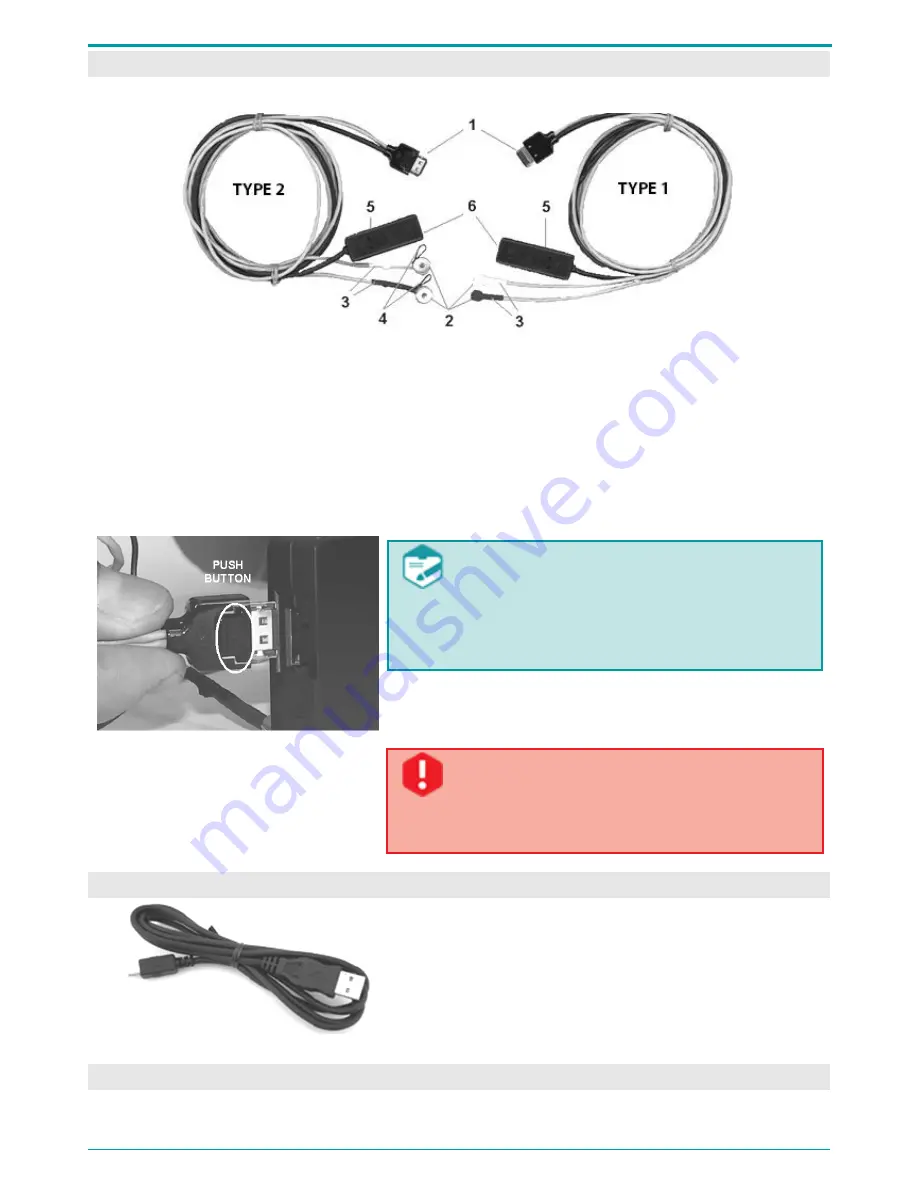
There are two microphone set options (Figure 2).
Figure 2: Microphone set
Both microphone sets include two mics 2 and remote control 5. Mic cables of left and right
channels 3 are marked with different colors: left channel mic is marked with darker color.
To prevent accidental disconnection from the device (4 on Figure 1) microphone plug is fitted up
with plunger pin. Each Type 2 microphone is also supplied with a wire loop 4 for fastening it to
clothes.
External microphones should be connected to the voice recorder to increase stereo base and
recording quality.
Figure 3: Connecting external microphone
When connecting external microphones or a
PC connection cable to the voice recorder,
make sure that the PUSH button on the plug
is directed opposite to the panel with device
serial number (Figure 3).
When disconnecting the cable from the recorder, first
press the PUSH button on the plug and then pull the plug
out.
Nonobservance of the instructions above
when plugging in/out external microphones
may lead to jack failure and recorder
malfunction.
6.4 US B C on n ec t i n g C a bl e
Figure 4: USB connecting cable
The recorder is connected to PC with a standard
USB-to-MicroUSB cable (Figure 4).
6.5 Po we r S u p pl y


