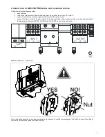
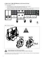
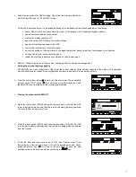
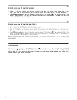
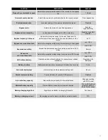
89
G
RAPHIC DISPLAY
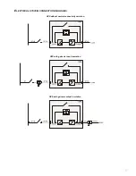
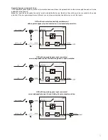
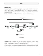
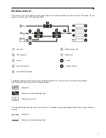
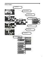
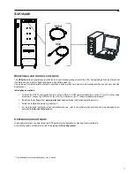
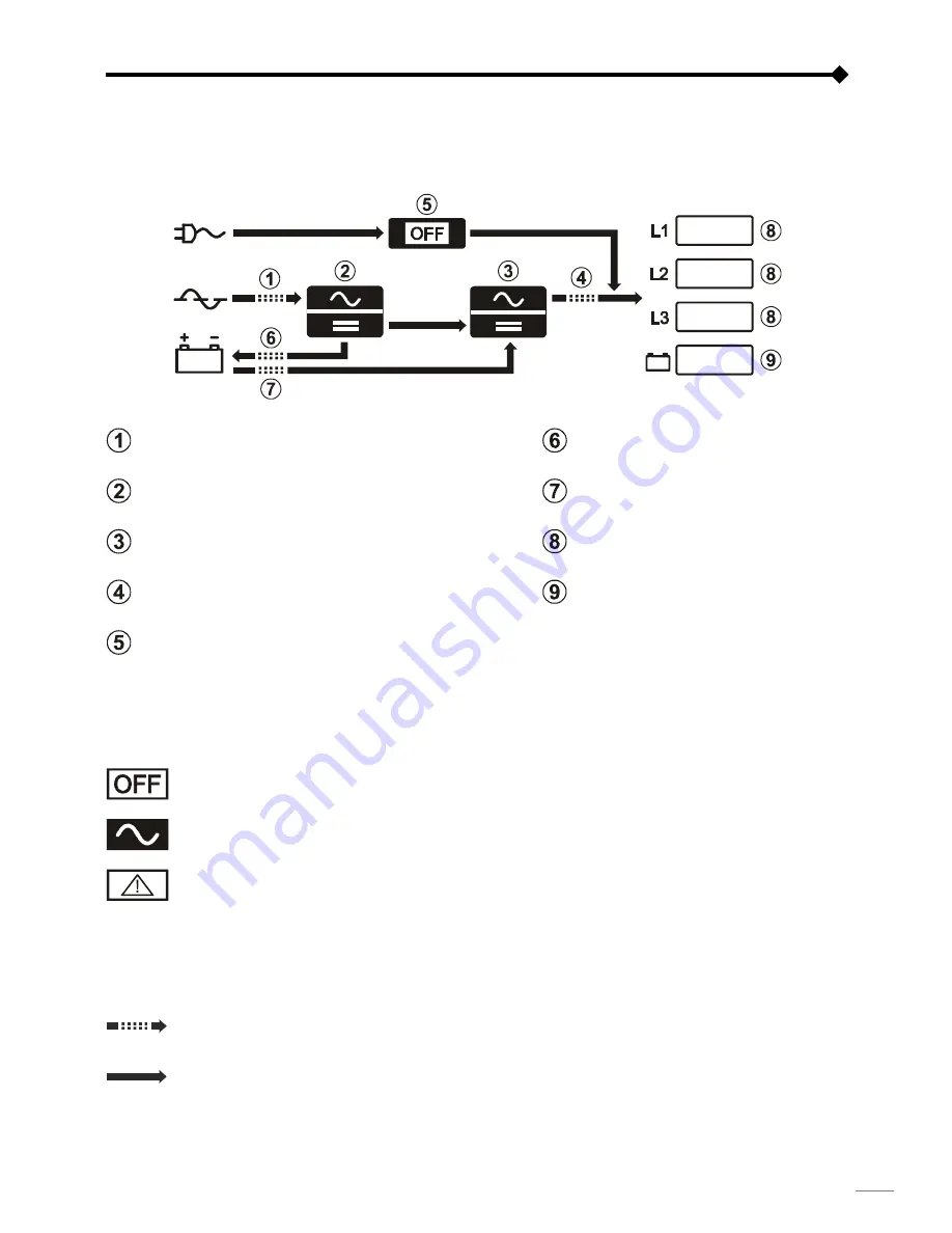
At the centre of the control panel is a wide graphic display for a constant detailed, real-time overview of UPS status. The first
page is a schematic view of UPS operating status:
Input Line
Battery Charger Line
PFC Converter
Battery Line
Inverter
% Load
Inverter Output Line
% Battery Charge
Automatic Static Bypass
The diagram shows the status of the three power logical modules (PFC Converter, Inverter, Automatic Static Bypass).
Each module can take on one of the following status types:
Module Off
Module on in normal operating mode
Module alarm or block
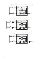
The following symbols show the power flow to and from the batteries (uncharged/charged) and the status of input and inverter
contacts:
Module Off
Module on in normal operating mode
Summary of Contents for GM 3100 PRO
Page 37: ...37 MENU DISPLAY ...
Page 91: ...91 DISPLAY MENU ...
Page 145: ...145 DISPLAYMENÜS ...
Page 199: ...199 MENU ECRAN ...
Page 253: ...253 MENÚ PANTALLA ...
Page 272: ......
Page 273: ......
Page 274: ......
Page 275: ...0MNMSTK60NP5LUD ...


