GMI PS200 ABC Handbook Download Page 45

4-5

INSTALL INSTRUMENT IN STATION & PERFORM BUMP / CALIBRATION

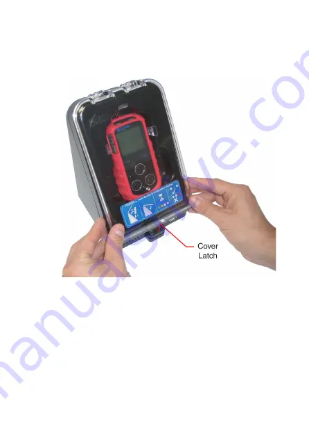
Close the front cover of the Auto Bump / Cal Station, as 

illustrated in Fig. 4-6, then, using both thumbs, press the lower 

edge corners of the cover firmly until the latch ‘clicks’ shut.

Fig. 4-6  Close Station Cover 

The Bump / Calibration operation starts up automatically 

following the locking of the station cover latch.

Summary of Contents for PS200 ABC

Page 1: ...Personal Surveyor 200 Auto Bump Calibration Station Handbook Gas Measurement Instruments Ltd...

Page 2: ...elcomes comments on all our publications Your comments can be of great value in helping us to improve our customer publications Please send any comments that you have to customerservice gmiuk com Copy...

Page 3: ...SOFTWARE authorised on the printed copy of the licence You may also store or install a copy of the network SOFTWARE on a storage device such as a network server used only to install or run the SOFTWA...

Page 4: ...ch defects in materials or workmanship GMI will replace the defective CD ROM or handbook The sole remedy for breach of this warranty is limited to replacement of defective CD ROM and handbook and or r...

Page 5: ...mitted TRADEMARK INFORMATION Windows XP Vista and 7 are registered trademarks or trademarks of the Microsoft Corporation in the United States and or other countries LIABILITY Every care has been taken...

Page 6: ...iv AUTO BUMP CAL STATION HANDBOOK...

Page 7: ...ence i 30 DAY LIMITED WARRANTY ii LIMITED WARRANTY ii COPYRIGHT iii TRADEMARK INFORMATION iii LIABILITY iii INTRODUCTION 1 1 1 1 GENERAL DESCRIPTION 1 1 1 2 AUTO BUMP CALIBRATION HARDWARE 6mm fittings...

Page 8: ...Cal Station if required 2 6 2 2 CONNECT POWER SUPPLY 2 8 VIEW RE CONFIGURE SOFTWARE 3 1 3 1 VIEW EDIT SOFTWARE CONFIGURATION 3 1 3 1 1 Quick Bump Test 3 5 3 1 2 Full Bump Test Factory Default 3 6 3 1...

Page 9: ...RODUCTION 5 1 5 2 DOWNLOAD TEST RESULTS 5 2 5 3 VIEW PRINT TEST RESULTS 5 4 Test Results 5 6 Generated Certificates 5 11 Certificate Content 5 12 Include Company Logo 5 13 Generated Certificate Files...

Page 10: ...viii AUTO BUMP CAL STATION HANDBOOK...

Page 11: ...urveyor 200 PS200 Series Auto Bump Calibration Station provides the user with a quick easy and reliable method of ensuring that PS200 series instruments are correctly calibrated where company policy d...

Page 12: ...mounting bracket and screws supplied with the unit Refer to APPENDIX A for fitting instructions Power is supplied to the rear of the unit via a 12V Universal Power Supply Unit PSU supplied with the u...

Page 13: ...e software configuration parameters can be edited via PC or Laptop then the settings file transferred to the Auto Bump Calibration Station using the USB memory stick supplied The software provides a f...

Page 14: ...Charging will take up to 4 hours to complete On completion a full battery symbol and CHARGING COMPLETE is displayed The instrument will not be damaged if left in Auto Bump Calibration Station after ch...

Page 15: ...mbi Test Gas Cylinder containing a mixture of 2 5 CH4 500ppm CO 50ppm H2S 18 O2 and balance N2 On Demand Gas Flow Regulator and Tubing 1 4 ADDITIONAL ACCESSORIES Combi Test Gas Cylinder GMI Part No 99...

Page 16: ...1 6 AUTO BUMP CAL STATION HANDBOOK...

Page 17: ...e Auto Bump Calibration Station from the Combi Test Gas Cylinder GMI Part No 99146 via an On Demand Flow Regulator GMI Part No 99118 and Tygon tubing complete with adaptor GMI Part No 64265 Fig 2 1 Ca...

Page 18: ...ibration The pressure gauge on the Regulator Valve after fitting gives a clear indication of this When applying gas to the instrument via the Auto Bump Cal Station it is important that the gas concent...

Page 19: ...window as illustrated in Fig 2 3 Software Configuration Gas Concentrations Fig 2 3 Software Configuration After comparing gas values between Cylinder Gas Label and Software Configuration when consist...

Page 20: ...e cylinder with one hand and turning the cylinder with the other Care must be taken not to over tighten the valve Fig 2 4 Attach Regulator Valve to Gas Cylinder Connect the barbed adaptor supplied wit...

Page 21: ...pplied an adaptor kit 6mm to 1 4 in is available as an accessory and supplied as a pack of 3 Part No 64085 The adaptor is fitted as illustrated in Fig 2 6 before connecting tubing Fig 2 5 Connect Gas...

Page 22: ...r is a push fit in the AIR inlet adaptor on the rear face of the station as illustrated in Fig 2 7 Air inlet tubing from the in line filter can be routed to the nearest window for the supply of fresh...

Page 23: ...ation The barbed adaptor is a push fit in the EXHAUST outlet adaptor on the rear face of the station Exhaust tubing can be routed to the nearest window Note that inlet and exhaust tubing must be dista...

Page 24: ...e station The plug adaptor is located in the 12Vdc socket on the rear face of the station as illustrated in Fig 2 8 Fig 2 8 Connect Power Supply to Station Locate the Universal Power Adaptor in a main...

Page 25: ...ns the PS200 Settings software in factory default configuration To view the default configuration settings insert the Memory Stick into an available USB port on your PC Laptop Depending on operating s...

Page 26: ...3 2 AUTO BUMP CAL STATION HANDBOOK Fig 3 2 Windows Vista Fig 3 3 Windows 7...

Page 27: ...t to both Handbook and the Quick Operation Guide as included in Auto Bump Cal Station package can be accessed from this window Adobe Acrobat Reader must be installed in your PC Laptop to view these fi...

Page 28: ...BUMP CAL STATION HANDBOOK Fig 3 5 Configuration Window Default Settings There are three available Bump Test Calibrate options Quick Bump Test Full Bump Test with option to calibrate failed ranges Cal...

Page 29: ...when using the GMI Test Gas Cylinder Part No 99146 To select this option position the cursor on the adjacent radio button then left click mouse button to confirm as illustrated in Fig 3 6 Fig 3 6 Qui...

Page 30: ...p test then if selected as illustrated in Fig 3 8 follow up with an automatic calibration of failed gas ranges if applicable Fig 3 8 Default Selection When gas is applied using the GMI Test Gas Cylind...

Page 31: ...To change calibration gas type a selection of flammable calibration gases are available as illustrated in Fig 3 9 Fig 3 9 Cal Gas Selection Calibration gases available for selection are as follows Me...

Page 32: ...libration Gas Values It is important that Testing Gases values displayed in window illustrated in Fig 3 10 are consistent with values displayed on gas cylinder label Fig 3 10 Gas Values To edit test g...

Page 33: ...to Bump Cal Station stored data and printed Test Calibration Certificate To change measurement units a drop down list is available as illustrated in Fig 3 11 Fig 3 11 Measurement Units Units available...

Page 34: ...the GMI Test Gas Cylinder Part No 99146 for a full 60 seconds and the Auto Bump Cal Station will record a Pass when the target values as listed in Testing Gases window illustrated in Fig 3 12 are att...

Page 35: ...To change calibration gas type a selection of flammable calibration gases are available as illustrated in Fig 3 13 Fig 3 13 Cal Gas Selection Calibration gases available for selection are as follows M...

Page 36: ...libration Gas Values It is important that Testing Gases values displayed in window illustrated in Fig 3 14 are consistent with values displayed on gas cylinder label Fig 3 14 Gas Values To edit test g...

Page 37: ...uto Bump Cal Station stored data and printed Test Calibration Certificate To change measurement units a drop down list is available as illustrated in Fig 3 15 Fig 3 15 Measurement Units Units availabl...

Page 38: ...Generate Settings File The Generate Settings File button illustrated in Fig 3 16 allows any configuration changes to be saved to USB Memory Stick as updated settings file then transferred to Auto Bump...

Page 39: ...data to USB Memory Stick 3 2 TRANSFER UPDATED PS200 SETTINGS SOFTWARE to AUTO BUMP CAL STATION Make sure that 12V power supply is connected to the Auto Bump Cal Station and switched ON indicated by a...

Page 40: ...uto Bump Cal Station indicated by three flashing green LED s as illustrated in Fig 3 18 Fig 3 18 Transferring Data to Auto Bump Cal Station On completion of downloading updated settings file the three...

Page 41: ...he 12V power supply is connected to mains wall socket Switch ON at mains Power to the unit is indicated by an illuminated green LED on the front of the station as illustrated in Fig 4 1 Fig 4 1 Statio...

Page 42: ...equence indicating that GMI TEST software has started Finally the ON indication is illuminated as illustrated in Fig 4 1 and theAuto Bump Cal Station is now ready for operation To release the front co...

Page 43: ...le in the station as illustrated in Fig 4 4 Note 1 The instrument can be either switched ON or OFF when inserted into the Auto Bump Cal Station Note 2 The Auto Bump Cal Station is designed so that the...

Page 44: ...4 4 AUTO BUMP CAL STATION HANDBOOK Push the instrument rearwards until correctly seated in the station recess as illustrated in Fig 4 5 Fig 4 5 Instrument Correctly Seated...

Page 45: ...the Auto Bump Cal Station as illustrated in Fig 4 6 then using both thumbs press the lower edge corners of the cover firmly until the latch clicks shut Fig 4 6 Close Station Cover The Bump Calibration...

Page 46: ...Bump Calibration operation starts up automatically following the locking of the station cover latch Fig 4 7 Perform Bump Calibration Immediately after the cover latch clicks shut the orange Test in P...

Page 47: ...overrides this and automatically switches OFF the instrument pump The six green LED s on the instrument flash in one second intervals then when the following instrument screen is displayed the gas de...

Page 48: ...ration setup from 15 seconds to 60 seconds Full Bump Test 60 seconds fixed Calibration 60 seconds fixed When the alarm setpoints are reached the instrument backlight illuminates red as illustrated in...

Page 49: ...re activated for a short period of time when each range reaches the instrument s configured alarm setpoint These normally overlap The station pump continues to operate for approximately 30 seconds in...

Page 50: ...e instrument fails please ensure you are using the correct gas cylinder and the cylinder contains enough gas to perform a bump calibration The pressure gauge on the Regulator Valve gives a clear indic...

Page 51: ...rom AUTO BUMP CAL STATION To release the front cover of the Auto Bump Cal Station press the cover latch downwards as illustrated in Fig 4 14 then open the cover fully Note that the front cover is desi...

Page 52: ...t as shown lean top of instrument away from station then carefully lift away from gas supply nozzle in the station as illustrated in Fig 4 15 Fig 4 15 Lift Instrument Clear of Gas Nozzle Close the fro...

Page 53: ...e Auto Bump Cal Station as follows Test Error A Test Error is indicated by a orange flashing LED as illustrated in Fig 4 16 Fig 4 16 Test Error If this fault occurs it is recommended that the Memory S...

Page 54: ...4 14 AUTO BUMP CAL STATION HANDBOOK...

Page 55: ...for viewing or printing The Memory Stick Part No 64184 containing GMI Settings software and supplied with the Auto Bump Cal Station must be used to download this data Fig 5 1 Downloading Memory Stick...

Page 56: ...tched ON and start up is completed This is indicated by an illuminated green ON LED on the front face of the station as illustrated in Fig 5 2 Fig 5 2 Station ON Indication Insert USB memory stick Par...

Page 57: ...wnloading Data This is followed by all four green LED s illuminating as illustrated in Fig 5 5 indicating that download is complete Fig 5 5 Download Complete Next LED s coloured orange orange and red...

Page 58: ...EST RESULTS Insert USB memory stick Part No 64184 into the USB port on PC Laptop Using Windows Explorer locate GMI PS200 SETTINGS program as illustrated in Fig 5 8 Fig 5 8 Locate Settings Program Posi...

Page 59: ...ed in package Part No 64186 Handbook Auto Bump Calibration Station User Handbook in PDF format Upload Folder Contains configuration settings used by Auto Bump Calibration Station Do not edit Test Resu...

Page 60: ...ation To access any of the above folders position cursor on required folder then double click mouse button to select Examples as follows Test Results The contents of this folder includes all instrumen...

Page 61: ...rticular instrument To open a test file position cursor on the file name then double click mouse button to select The following example Fig 5 11 illustrates information available including Instrument...

Page 62: ...5 8 AUTO BUMP CAL STATION HANDBOOK EXAMPLE Fig 5 11...

Page 63: ...e Memory stick has been used to download data from Each file contains a list of all instrument serial numbers tested on that particular station Each rec file can be opened individually to display prin...

Page 64: ...5 10 AUTO BUMP CAL STATION HANDBOOK Fig 5 12 Tested Instruments on 000101 The file includes A list of instruments tested Date Tested day month year Time Tested Test Result P PASS or F fail...

Page 65: ...l Bump Test Calibration Certificates generated when selecting the View Test Calibration Certificate button in the configuration window as illustrated in Fig 5 13 The configuration window can be access...

Page 66: ...ed in a Certificate Printer window accessed by clicking mouse button on View Test Calibration Certificate button in the configuration window illustrated in Fig 5 13 The Certificate Printer window is d...

Page 67: ...18 Include Company Logo To include your company s logo on printed certificate insert the logo file named logo jpg into the Generated Certificates folder on the Memory Stick Part No 64184 The logo will...

Page 68: ...enerated Certificate Files Each html file can be opened individually to display print a Bump Results Calibration Certificate Note If background image green tick illustrated in Fig 5 17 or 5 18 is not...

Page 69: ...5 15 VIEW PRINT TEST RESULTS Fig 5 17 Bump Results...

Page 70: ...5 16 AUTO BUMP CAL STATION HANDBOOK Fig 5 18 Calibration Certificate...

Page 71: ...1 GENERAL DESCRIPTION The GMI Personal Surveyor 200 PS200 Series Auto Bump Calibration Station is supplied with a mounting bracket and necessary screws to secure the station to a workbench or similar...

Page 72: ...loth or similar on workbench to protect Bump Cal Station front cover surface from scratching and or scuffing 3 Carefully place Bump Cal Station face down on workbench Refer to Fig A 2 Fig A 2 Attach B...

Page 73: ...Bump Cal Station as illustrated in Fig A 2 6 Using a No 2 Pozidrive screwdriver tighten all four screws to secure 1 3 ATTACH STATION to WORKBENCH DAISY CHAIN OPTION The bracket can be secured to a wo...

Page 74: ...al Stations can be connected in a daisy chain fashion by using a double sems pozi pan screw supplied Part No 24957 through bracket at rear of station and into captive nut of adjoining bracket Refer to...

Page 75: ...UMP CALIBRATION HARDWARE 1 4 Bump Cal Station Tested Instruments 5 9 Bump Test 3 5 3 6 C Calibration 3 10 CALIBRATION GAS 2 1 Calibration Gas Type 3 11 Calibration Gas Values 3 12 CALIBRATION HARDWARE...

Page 76: ...T INDICATION 4 13 Files Certificate 5 14 File Settings 3 14 FIT MOUNTING BRACKET A 2 Full Bump Test Factory Default 3 6 G GAS CALIBRATION 2 1 Gas Cylinder Label 2 2 Gas Type 3 11 Gas Values 3 12 GENER...

Page 77: ...ESULTS 5 1 5 4 Q Quick Bump Test 3 5 R REMOVE INSTRUMENT from AUTO BUMP CAL STATION 4 11 Results Test 5 6 RESULTS TEST 5 1 S Settings File 3 14 Software Configuration 2 2 SOFTWARE EDIT 3 1 Software Li...

Page 78: ...iv AUTO BUMP CAL STATION HANDBOOK V Values Gas 3 12 VIEW EDIT SOFTWARE CONFIGURATION 3 1 VIEW PRINT TEST RESULTS 5 1 5 4 W WARRANTY LIMITED ii...

Page 79: ......

Page 80: ...0 141 812 7820 sales gmiuk com www gmiuk com Service Calibration Centre 25 Cochran Close Crownhill Milton Keynes England MK8 0AJ Tel 44 0 1908 568 867 Fax 44 0 1908 261 056 service gmiuk com Service C...

Reviews: