background image

PIN POINTER

PIN POINTER

This system is used to determine the presence of a metal target or cavity with the precise identifi-
cation of the location in which the metal or buried cavity is located through a sound or graphic 
displayed on the screen or visual representation on the tablet.
The scanning process is conducted for potential targets via the V.S.T probe, but with the selection 
of the Pin Pointer System.

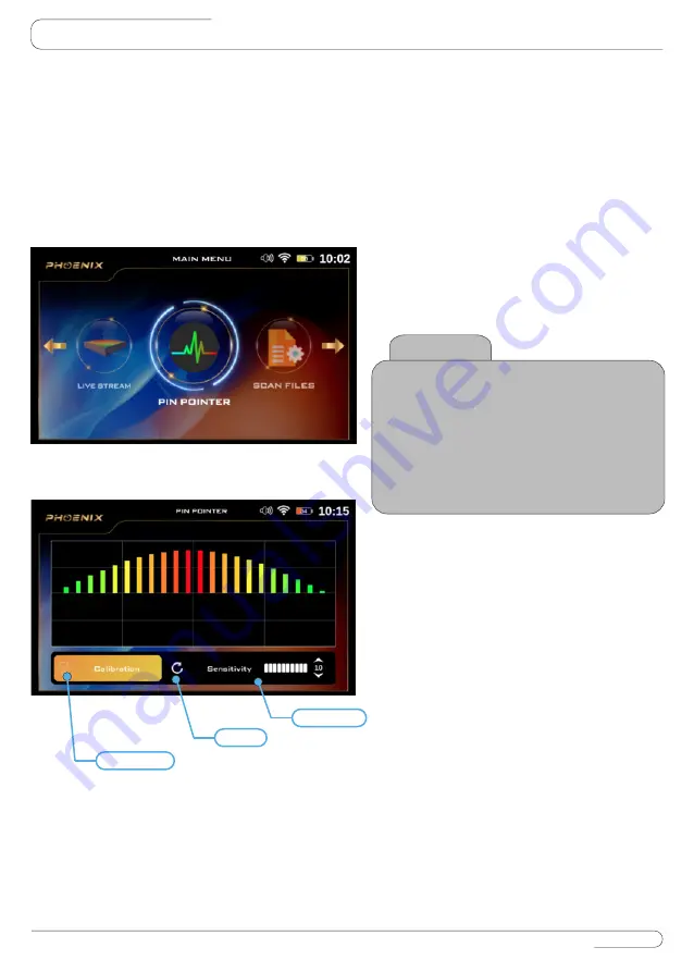
To get started, select Pin Pointer System from 
the main menu and press OK
After the selection, a Pin Pointer system 
screen will appear, which includes the follow-
ing elements:

Select the system

Sensitivity

Calibration

During the search process and according to 
the target scan, the device will make a special 
sound tone with a graphical presentation on 
the screen that represents the presence of the 
target underground.
User can change the sensitivity value at any 
time to control the output sound and visual-
ization on screen.

Reset

Use this button to return the calibration to the 
default value.

User can use this option to calibrate the probe 
sensitivity at any time according to the type of 
ground and the condition of the area to be 
scanned.

Calibration

Reset

Sensitivity

32

Notice

Immediately after entering any search 

system from the main menu, A video will 

appear which notify the device's assembly 

steps. In case of any mistake in the 

assembly or installing a wrong part that 

does not fit the selected system, a 

warning video will appear on the device's 

screen regarding the exact error

Summary of Contents for MEGA DETECTION GOLDSTAR 3D SCANNER

Page 1: ...Set of Detection Tools for Professional Treasure Hunters SEARCH SYSTEMS Most Powerful 3D Ground Scanner Complete Solution for Professional Treasure Hunters Unearth All Buried Deep Treasures Visually N...

Page 2: ...USER MANUAL...

Page 3: ...e Contents Overview Assembly V S T Assembly Ground Scan Assembly Stack Holder Panel Keys Settings Ground Scan System Scan Files Live Stream System Pin Pointer System Multi Visual Analyzer Costumer Ser...

Page 4: ...not use the device indoors The device may constantly give target signals indoors as there are many metals Use the device outdoors in open fields Do not submerge the device or its accessories in water...

Page 5: ...ial incidental or consequential damages including damages for interest loss business loss loss of use or data business interruption and the like even if the company was notified of the possibility of...

Page 6: ...transmitter and receiver probe which provide professional surveying tools to scan the ground to large depths accurately and quickly with visual representation of the scanning results on the device scr...

Page 7: ...PACKAGE CONTENT 1 2 4 A B C D E F 3 5 6 7 11 12 9 10 6 8...

Page 8: ...k Shaft M G S 60 Scanner Long Range Antennas x2 Headphones Armrest Holder Accesories Box including A M G S Screw and Nut x2 B Washer for Plastic Stick Shaft C Armrest Holder Screws Spare Parts D Unive...

Page 9: ...LIVE STREAM SYSTEM PIN POINTER SYSTEM OVERVIEW 8 GROUND SCAN SYSTEM...

Page 10: ...ASSEMBLY 1Connect V S T Sensor to the device as it shown in the picture 2 Use the power jack to connect the battery Live Stream System Pin Pointer System 9 Power Jack...

Page 11: ...lower pipe using the speci c screw and nut 3 Attach the battery to the hand holder so that the battery clip is in its speci c place 4 Connect the scanner cable into the connector base 5 Put the devic...

Page 12: ...ach the main unit on the holder 1 Prepare the main unit and the stack unit 2 Fit the main unit and the holder rail as Parallel position 3 Put the main unit into the rail until you hear a sound come fr...

Page 13: ...ASSEMBLY 1 2 De attach the main unit from the holder Lock pin 1 Press the Lock pin on the holder 2 Pull the main unit to front side 12...

Page 14: ...ise 2 t the main unit as the prefared degree and Close the screw again 13 To t the view degree of main unit on the holder there is an option users can use This option helps to t device position on hol...

Page 15: ...PANEL KEYS 1 Power Key 3 OK Key 2 Back Key Backward 4 Home Key 5 Control Settings Arrow Keys Right Left Up Down OK OK 5 4 3 2 1 14...

Page 16: ...the main menu To turn off the main unit just press the power key when confirmation message appears choose Yes to confirm or No to cancel after power off the device press two time on battery power but...

Page 17: ...r setting each one Press to save 2 Use top down arrows to select Set Date then press OK OK OK 16 4 After adjusting the setting press back on device controls key Use this option to save power when usin...

Page 18: ...OK OK 17 After adjusting the setting press back on device controls key After activating the previous option the securi ty lock code can be set by the Set Security Code option When operating the device...

Page 19: ...s in the device will revert to the factory defaults and the memory data will be erased 2 Clear Memory By using this option the memory Data will be erased you can control screen settings using this men...

Page 20: ...is option to control the sound of the whole device Keypad Volume Use this option to control the keypad sound volume Scan Volume Use Up Down arows to select the sound sett ng you need to change and the...

Page 21: ...SETTINGS This screen includes all device information 1 Device Version 2 Software version 3 Device Model 4 Serial Number 5 Country of manufacturer 20...

Page 22: ...a completely new system in new Mega Detection devices with new and improved technology This system helps the user to scan the ground and create a 2D visualization on the device screen or 3D visualizat...

Page 23: ...he Up Down arrows then press the OK key Height Steps This number expresses the number of scanning steps or points for each line and it can be changed by using the Up Down arrows and then pressing the...

Page 24: ...ly start the scanning process After the setup is complete make sure that the device is fully and correctly assembled Hold the device in the following manner and make sure that you are holding the devi...

Page 25: ...0 Cm 24 If there is an uneven area of land first clean the area and arrange it as flat as possible before performing the actual scan Continue scanning step by step according to the scanning path you s...

Page 26: ...ess is completed you will see an alert on the screen stating that the scanning process is complete press OK to exit During the scanning process you will see the color change of each cell of the grid a...

Page 27: ...aved file Delete Select this option to delete the current file Cancel Select to cancel opening the file and return to the file list You can choose the Scan Files option from the main menu then press t...

Page 28: ...ning results screen After clicking on the search icon use the arrow keys on the keyboard to select a specif ic cell To return to the scanning tools press the back button Selected Tile 27 Notice The us...

Page 29: ...ts an average value of all values in the detected points Depth When the selection is made on the cell the depth value will appear in the lower informa tion bar and the user can see the depth in each c...

Page 30: ...als captured by the V S T probe are represented on the screen of the device as a continu ous color stream that changes colors according to the type of potential target Similarly the color will be red...

Page 31: ...a target underground or not On the right side of the screen there is 3 boxes which are Value It directly indicates the value of the signal captured by the search sensor The colors of the indicator ch...

Page 32: ...connotations of different colors Red gold or large pieces of metal target Green nornal natural ground Light Blue a small cavity Blue a larg voids like a tunnel Yellow a small piece of metal object 31...

Page 33: ...ss and according to the target scan the device will make a special sound tone with a graphical presentation on the screen that represents the presence of the target underground User can change the sen...

Page 34: ...e or pivot or even swing On the screen of the device a bar graph is displayed that appears in green in the case of a natural ground in the case of receiving metal signals a graph which includes rectan...

Page 35: ...Step 5 Enter this password phoenix3d Step 6 open Multi Visual Analyzer app in tablet note if all 6 steps above done correctly you will hear a voice coming from the tablet saying CONNECTED SUCCESSFULL...

Page 36: ...rm the scan automatically with the interval that is mentioned in part C F Scan Pattern This option includes two items parallel zigzag User can choose which kind of pattern want to use during scan MULT...

Page 37: ...enable disable depth value for each point on the 3D graph MULTI VISUAL ANALYZER 36 Files After each ground scan job a file will create which includes all data about this job This file is saved inside...

Page 38: ...l change like the picture below This screen includes three items 1 Live Stream view this view is showing the live stream result Description about this view and colors in this box was coming in this us...

Page 39: ...droid device a connection between both the device and the app will be established but if not happened because of any reason user can do it manually by using Connection item in the settings menu Animat...

Page 40: ...nce services are only available at GMI accredited centers GMI is not responsible for the warranty or maintenance of any damage arising out of the use of accessories from other sources You can get all...

Page 41: ...T LCD Screen Size 5 Inch Screen Resolu on 1024 x 860 Colors 16 million Wi Fi Connec on 2 4 Ghz Sound Output Speaker Headset Jack Type 3 5 mm Headset Wired Headphones Internal Speaker Yes Power Ba ery...

Page 42: ...st distributor www Megalocators com where to buy For product validation you can check the product serial number by the link below www Megalocators com product validation Geophysical Measuring Instrume...

Reviews: