


17
221129A
9 E l e c t r i c a l C o n n e c t i o n s
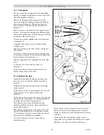
Diagram 9.2
2643
1
2
3
N
L
E
RED LINK
Remove when
connecting any
heating system
controls.
CABLE
CLAMP
MAINS
CABLE
COVER
SCREW (2)
9.1 Supply Cable Connection
CAUTION: To prevent an induced current from
switching the central heating on, when not required, it is
important that the heating system control cables are
separated from the other mains supply cables.
The boiler requires a permanent mains supply through an
external isolator which must also isolate any heating
system controls, see diagram 9.1.
Any heating system controls must not interrupt the
permanent mains supply to the boiler.
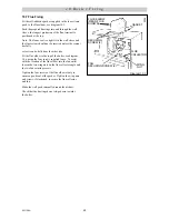
Remove the electrical connector from the loose
items pack.
Remove the two screws and cover from the connector,
see diagram 9.2.
Using PVC cable of a suitable length and rating as stated
in Section 1.8 “Electrical Supply”, connect the mains
supply cable to the appropriate terminals of the
connector, see diagram 9.1.
Standard colours are, Brown - Live, Blue - Neutral,
Green and Yellow - Earth.
The mains cable outer insulation must not be cut back
external to the plug, see diagram 9.2.
Make the earth cable of a greater length so that if the
cable is strained the earth would be the last to become
disconnected.
CAUTION: It is ESSENTIAL to make sure that the
polarity is correct.
9.2 Heating System Controls
CAUTION: To prevent an induced current from
switching the central heating on, when not required, it is
important that the heating system control cables are
separated from the other mains supply cables.
It is recommended that the heating system is controlled
by a time switch and a room thermostat, or alternatively
by thermostatic radiator valves.
If electrical controls are not to be used to regulate the
heating system, do not disturb the red link cable.
If any form of electrical control is being used to regulate
the heating system, remove the red link cable and
connect heating system controls in series.
The mains cable outer insulation must not be cut back
external to the plug.
9.3 Clock/Timer Kit
An internal clock/time kit can be supplied, refer to the
instructions supplied with it.
9.4 Frost Thermostat
If the installation requires protection by a “frost
thermostat”, connect a single pole type, to the
appropriate terminals of the connector.
9.5 Cable and Connector Securing
After completing all the connections to the boiler, secure
the cable(s) with the cover, using the two screws
previously removed, see diagram 9.2.
Clip the connector into position with the cable(s) at
the back.
Secure all cables in the clamp immediately behind the
connector.
If necessary also secure cables to the wall, using suitable
cable clips.
Keep all cables away from hot surfaces.


