Supplied By www.heating spares.co Tel. 0161 620 6677
9
220562A
5 L i g h t i n g , T e s t i n g a n d F i t t i n g I n t e r n a l P a r t s .
Diagram 5.1
Air may be present in the supply to the fire so that the
initial lighting operation may need to be repeated.
With the burner lit. Check joints at all tap positions for
gas soundness in accordance with the current issue of
BS6891.
To change settings, refer to diagram 5.4.
Check that the gas pressure is as stated in the Data
Section or on the Data Label.
If there is any doubt about the gas rate, check at the
meter, having turned off all other gas appliances and
pilot lights.
The gas rate for this fire front is about 0.63m
3
/h
(17.75ft
3
/h), equal to, after 10 minutes, about 3 minutes
23 seconds for 1ft
3
.
Push in and turn the control knob fully clockwise to turn
off, remove the pressure gauge, replace the test nipple
screw and ensure that a gas tight seal is made.
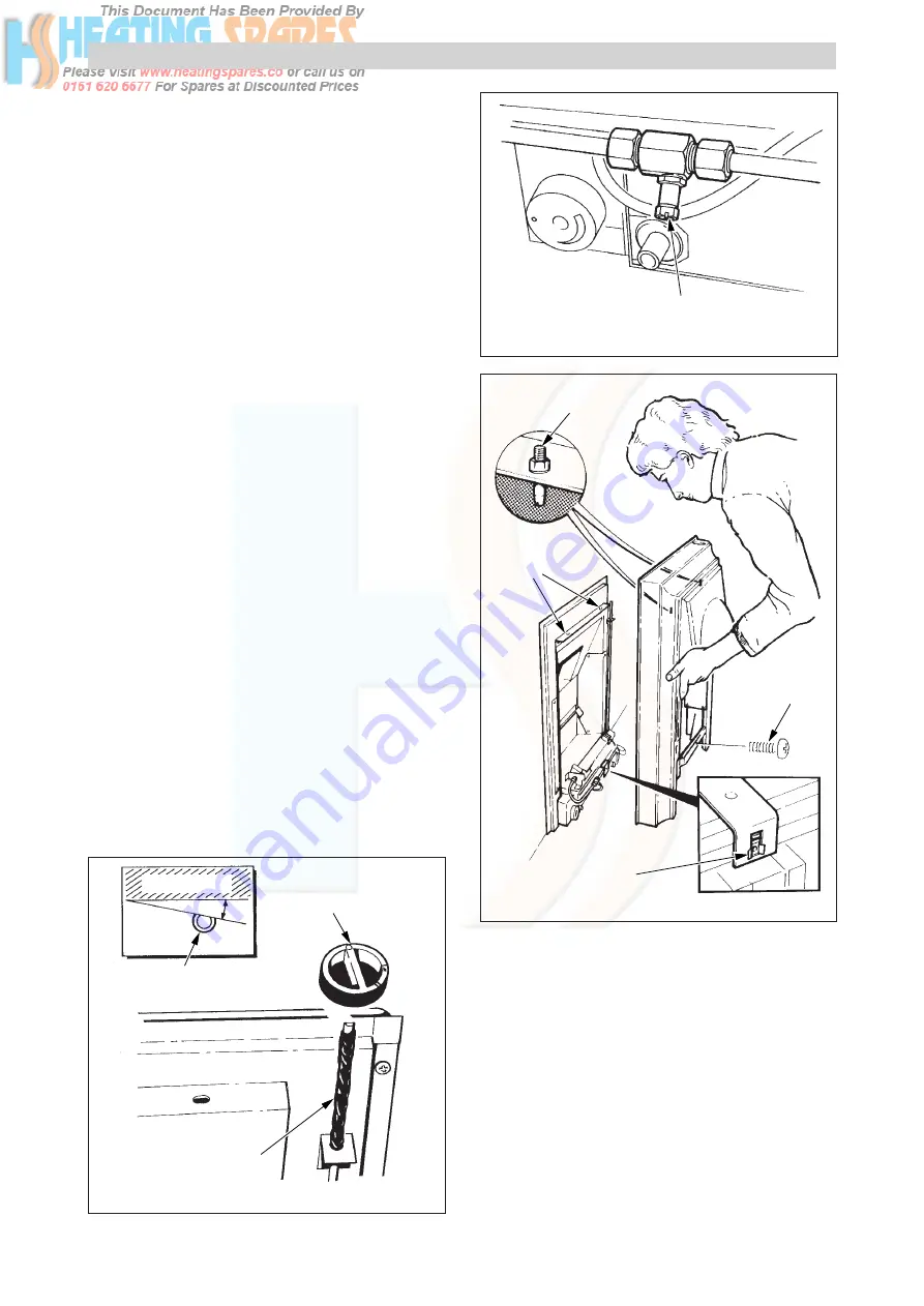
5.2 Fire Front
Remove the castings from the packaging.
Lift the fire front up, take care as it is heavy, and slide it
down to locate the pins into the brackets, see
diagram 5.3.
Secure the fire front to the combustion chamber
assembly (base), using the M4 screw provided in the
loose items pack, see diagram 5.3.
WALL LINE
12˚
DRIVE ROD
Flat facing the wall
INSULATION SLEEVE
CONTROL KNOB
3517
Diagram 5.2
PRESSURE
TEST POINT
4020
Diagram 5.3
4017
LOCATION
PEG (2)
LOCATION
HOLES
FIRE
FRONT
SECURING
SCREW
FIRE FRONT
RETAINING
NUT


