38
221680G
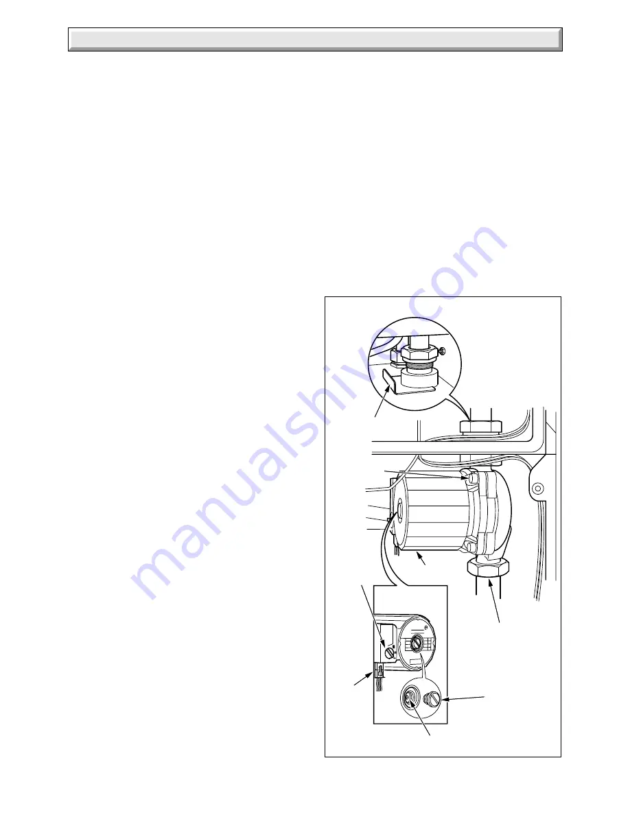
Diagram 14.16
7033
PUMP
CLIP
UNION
NUT
END
SCREW
SPINDLE
SECURING
SCREW (4)
PUMP
ADJUSTER
PLUG
14 Replacement of Parts
Disconnect the pressure gauge connection from the safety
valve, see diagram 14.12.
Disconnect the union nuts to release the safety valve, see
diagram 14.12.
Discard the sealing washers and use the new ones supplied, on
assembly.
Make up water loss and pressurise the system, refer to
Commissioning in the Installation Instructions.
14.21 Water Inlet Filter
Before starting refer to Section 11.
Remove the case base, see diagram 10.4.
Isolate domestic water inlet, release the domestic water pressure
and drain by opening the draw off lowest tap, refer to Section
11.3 and 11.6.
Disconnect the water inlet union nut to gain access to the filter,
see diagram 8.4.
Clean or renew the filter as necessary.
Discard the sealing washer and use the new one supplied, on
assembly.
14.22 Pump
Before starting refer to Section 11.
Open the controls cover door. Remove the two screws securing
the controls facia, see diagram 9.1.
Hinge the control fascia open.
Remove the electrical plug at the pump, see diagram 14.16.
Release the water pressure and drain, refer to Sections 11.3
and 11.6.
Disconnect the pump at the top in the combustion chamber by
removing the union nut and clip, see diagram 14.16.
Rlease the union nut at the bottom of the pump, see diagram
14.16.
It may be necessary to slacken the union nut at the automatic
bypass and water cock.
Remove the pump.
Discard the sealing washer from the bottom fixing.
Make sure that the flow direction arrow is pointing upward, on
the pump, when fitting the pump to the lower pipework use the
new sealing washer provided.
Set the flow adjuster on the pump to maximum setting. The flow
rate should be controlled by means of a valve in the heating
system.
Make up water loss and pressurise the system, refer to
Commissioning in the Installation Instructions.
Note: Should the pump fail to work, see diagram 14.25. If all is
in order but the pump still does not work, remove the screw, see
diagram 14.16 then turn the pump spindle to release any
temporary seizure. DO NOT HIT THE SPINDLE.
14.23 Flow Sensor
Before starting refer to Section 11.
Remove the case base, see diagram 10.4.
Remove the main burner, refer to Section 14.2.
Refer to diagram 14.18.
Disconnect the domestic inlet pipe.
Remove the water flow sensor assembly.
Disconnect the electrical plug.
Unscrew the water flow sensor and remove.
Ensure sealing washers are in place when refitting.
14.24 Automatic Air Vent
Before starting refer to Section 11.
Release the water pressure and drain, refer to Sections 11.3
and 11.6.
Remove the automatic air vent, see diagram 14.17.
Discard the sealing washer and use the new one supplied,
when fitting.
Slacken the small cap on the air vent. This MUST NOT be
retightened.
Make up water loss and pressurise the system, refer to
Commissioning in the Installation Instructions.


