24
2000225000B
5mm
4mm
8mm
SPARK GAP
SENSE GAP
15 Routine Cleaning and Inspection
15.6 Side panels (for ease of access if
required), refer to diagram 15.4.
• Support the side panels as you remove them.
• Unscrew and remove the three retaining screws from front of
each side panel.
• Left hand side panel only disconnect the control panel retaining
strap at the control panel.
• Pull each panel forward from the rear retaining pins to remove.
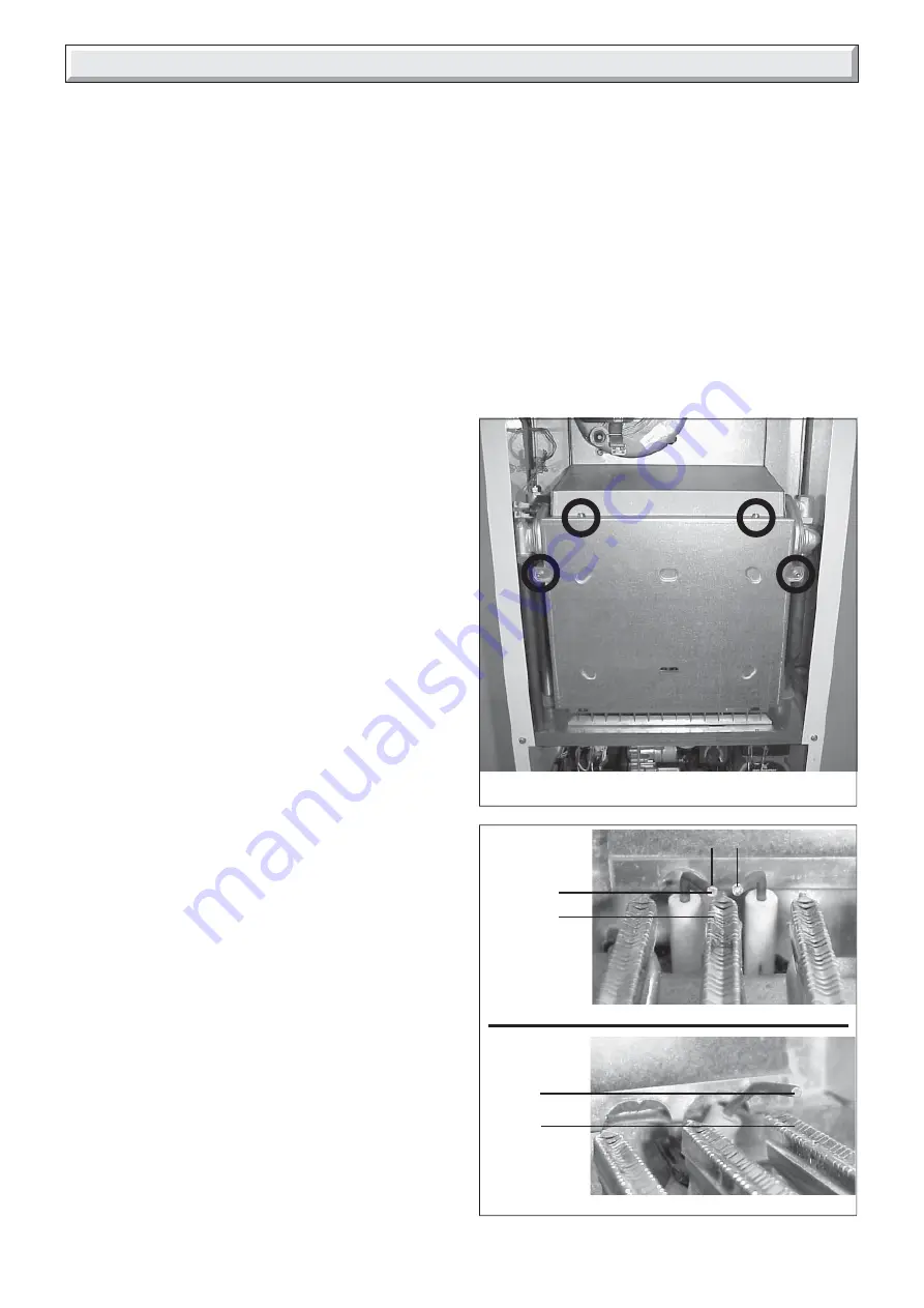
15.7 Combustion chamber cover
• Unscrew and remove the four screws securing combustion
chamber cover to combustion chamber,
see diagram 15.5
.
• Remove combustion chamber cover from boiler.
• Take care not to damage the insulation.
15.8 Spark and Sense Gaps
• Check that the spark and sense gaps as shown in
diagram
15.6.
Note: To gain access to spark and sense electrodes for
removal, refer to
Section, 18.12 and 18.13 in Replacement of
Parts
.
15.9 Burner, refer to diagram 15.7.
• Unscrew and remove the two burner retaining screws.
• Remove burner from boiler by easing it forward off the two
burner guides.
• Clean burner by washing in soapy water. Dry thoroughly
before refitting.
Note: To gain access to injectors for removal and cleaning, refer
to
Section, 18.8 in Replacement of Parts
.
15.10 Fan, refer to diagram 15.8.
• Disconnect power supply leads and earth lead from fan.
• Remove air pressure switch sensing tube from the side of the
fan.
• Unscrew and remove the fan retaining screw.
• Ease the fan down and forwards to remove.
15.11 Heat exchanger, refer to diagram 15.9.
• Remove the two flue hood retaining screws to remove the flue
hood.
• Use a soft brush or vacuum clean the heat exchanger.
DO NOT USE ANY TOOL LIKELY TO DAMAGE PAINTED
FINISH OF HEAT EXCHANGER.
15.12 Domestic water inlet filter, refer to
diagram 15.10.
If the water flow rate through the appliance has reduced it may
be necessary to clean or replace the domestic water inlet filter.
• Pull out slotted clip securing the filter in its housing, remove the
filter to clean or renew if necessary.
Replace the filter into its housing and replace the securing clip.
• Open isolating valve
(c)
on cold water inlet and test the
Domestic Hot Water circuit for soundness.
Diagram 15.6
9979
9978
Diagram 15.5
15.13 Central Heating Filter, refer to diagram
15.11.
Remove the filter retaining clip and filter clean or renew if
necessary
.
Refit the filter, ensuring the correct orientation. The flat and hole
in the filter as shown. Secure with retaining clip.
15.14 Reassembly of parts removed for
servicing
All parts are replaced in reverse order to removal.
15.15 Flue system
• Check externally to make sure that flue is not blocked
• Inspect flue system to make sure that all fittings are secure.
9980


